Download
1 / 18

E N D
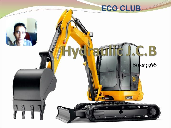
ECO CLUB Hydraulic J.C.B Boss3366
(1)Introduction Today in modern era people use diesel JCB but in this time student make Hydraulic JCB. Which was movement with the Hydraulic Pressure. It was without Pollution. In little model student use injection. Its fill injection with the water which is join with the help of a pipe another injection. Then after it became movement..,
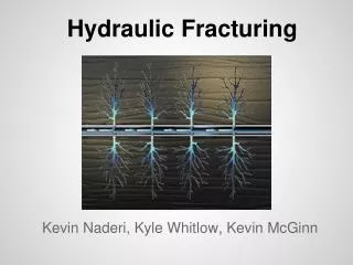
(2)Hydraulic Principles • Hydraulic systems provide a means of remotely controlling a wide range of components by transmitting a force through a confined fluid. • Because hydraulics can transmit high forces rapidly and accurately along lightweight pipes of any size, shape and length, they are the prime source of power in aircraft systems such as flying controls, flaps, retractable undercarriages and wheel brakes. • The basic principle behind any hydraulic system is very simple - pressure applied anywhere to a body of fluid causes a force to be transmitted equally in all directions, with the force acting at right angles to any surface in contact with the fluid.
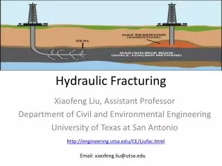
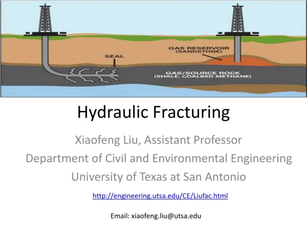
For the instruction of hydraulic principles • Pascal's Law • Hydraulic Pressure and Force • Hydraulic Swash Plate Pump
Pascal's Law • Pascal's Law (from Blaise Pascal 1623 to 1662), comprises a set of principles formulated in 1648 and states that pressure applied to a confined fluid at any point is transmitted undiminished throughout the fluid in all directions and acts upon every part of the confining vessel at right angles to its interior surfaces and equally upon equal areas. • This is the basic principle behind any hydraulic system - pressure applied anywhere to a body of fluid causes a force to be transmitted equally in all directions, with the force acting at right angles to any surface in contact with the fluid. A demonstration of Pascal's Law
Hydraulic Pressure and Force • Pressure is the force per unit area exerted on a surface, divided by the area of that surface. • Pressure = Force/Surface Area • Therefore hydraulic pressure is the force per unit area exerted by a fluid on the surface within the container. The relationship between hydraulic pressure and force
Hydraulic Swash Plate Pump • A constant displacement hydraulic pump uses a fixed swash plate to drive a set of pistons in and out as they revolve. • At the top of their stroke, the pistons move over the inlet port and draw in fluid at low pressure. The fluid is then carried round and expelled through the outlet port at high pressure as the swash plate drives the piston into the cylinder. A constant displacement hydraulic swash plate pump.
Hydraulic Principles • Fluids cannot be compressed • Fluids can transmit Movement • Acts “Like a steel rod” in a closed container • Master cylinder transmits fluid to wheel cylinder or caliper piston bore. • Fluids can transmit and increase force Force Pressure Area
Hydraulics • Simplified Hydraulic Brake System • Drum Brake • Master Cylinder • Disk Brake
(3)Hydraulic pump Hydraulic pumps supply fluid to the components in the system. Pressure in the system develops in reaction to the load. Hence, a pump rated for 5,000 psi is capable of maintaining flow against a load of 5,000 psi. Pumps have a power density about ten times greater than an electric motor (by volume). They are powered by an electric motor or an engine, connected through gears, belts, or a flexible elastomeric coupling to reduce vibration.
Common types of hydraulic pumps to hydraulic machinery applications are- • Gear pump: cheap, durable, simple. Less efficient, because they are constant (fixed) displacement, and mainly suitable for pressures below 20 MPa (3000 psi). • Vane pump: cheap and simple, reliable (especially in g-rotor form). Good for higher-flow low-pressure output. • Radial piston pump A pump that is normally used for very high pressure at small flows. Piston pumps are more expensive than gear or vane pumps, but provide longer life operating at higher pressure, with difficult fluids and longer continuous duty cycles. Piston pumps make up one half of a hydrostatic transmission.
(4)Hydraulic jack Hydraulic jacks are typically used for shop work, rather than as an emergency jack to be carried with the vehicle. Use of jacks not designed for a specific vehicle requires more than the usual care in selecting ground conditions, the jacking point on the vehicle, and to ensure stability when the jack is extended. Hydraulic jacks are often used to lift elevators in low and medium rise buildings. Jackscrews are integral to the Scissor Jack, one of the simplest kinds of car jacks still used. A hydraulic jack uses a fluid, which is incompressible, that is forced into a cylinder by a pump plunger. Oil is used since it is self lubricating and stable. When the plunger pulls back, it draws oil out of the reservoir through a suction check valve into the pump chamber. At this point the suction ball within the chamber is forced shut and oil pressure builds in the cylinder.
In a bottle jack the piston is vertical and directly supports a bearing pad that contacts the object being lifted. With a single action piston the lift is somewhat less than twice the collapsed height of the jack, making it suitable only for vehicles with a relatively high clearance. For lifting structures such as houses the hydraulic interconnection of multiple vertical jacks through valves enables the even distribution of forces while enabling close control of the lift. In a floor jack (aka 'trolley jack') a horizontal piston pushes on the short end of a bellcrank, with the long arm providing the vertical motion to a lifting pad, kept horizontal with a horizontal linkage. Floor jacks usually include castors and wheels, allowing compensation for the arc taken by the lifting pad. This mechanism provide a low profile when collapsed, for easy maneuvering underneath the vehicle, while allowing considerable extension.
(5)Hydraulic Crane We manufacture a wide range of hydraulic cranes that are truck mounted and made from superior quality raw materials. These cranes are developed as per the specifications of our collaborator HEILA, Italy. For handling any type of load, our products are offered with: • Hydraulically operated telescopic or articulated boom• Balanced compact Hydraulic Winch• Hydraulically operated Grab Bucket to secure any type of configuration of the load.
These cranes are capable of handling loads between 2 tone meter to 35 tone meter. Available with hydraulic slewing arrangement up to 380 degree, these cranes are capable of picking load and keeping in any direction. This arrangement require minimum space in truck leaving major portion of truck empty for self loading. We also offer 2 points or 4 points hydraulic stabilizers with our cranes as desired by our clients. In order to ensure complete safety, we offer with our products: overload protection valve, Hose Fail Safety Valve that helps in adjusting pressure in case of excessive load and also ensure that cylinder does not come down with load in case of power failure. Designed to perfection, our products can easily mount on trolley, trailer, barge or stationary base easily.
Used of Hydraulic J.C.B By using a proportional ‘soft stop’ system on the higher lift machines, Adaptive Load Control overcomes the problem caused by a sudden stop creating additional inertia from a combination of weight and high reach, that can increase the risk of machine forward overturn. The proportional flow reduction used for the high reach machines also maximises speed of operation so that the operator’s ability to use the machine’s full operating envelope is not compromised. – The lift performance indicated on the lift chart can be achieved while complying with EN15000 using the Adaptive Load Control system
Thank you Made by:-Ankush dhaka,Sandeep kumar,Nikhil sharma