Download
1 / 35
460 likes | 830 Views
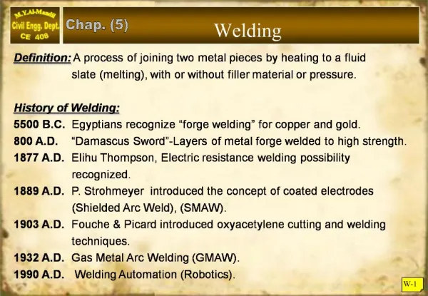
Welding. Chap. (5). Definition: A process of joining two metal pieces by heating to a fluid slate (melting), with or without filler material or pressure. History of Welding: 5500 B.C. Egyptians recognize “forge welding” for copper and gold.

E N D
Welding Chap. (5) Definition: A process of joining two metal pieces by heating to a fluid slate (melting), with or without filler material or pressure. History of Welding: 5500 B.C. Egyptiansrecognize “forge welding” for copper and gold. 800 A.D. “Damascus Sword”-Layers of metal forge welded to high strength. 1877 A.D. Elihu Thompson, Electric resistance welding possibility recognized. 1889 A.D. P. Strohmeyer introduced the concept of coated electrodes (Shielded Arc Weld), (SMAW). 1903 A.D. Fouche & Picard introduced oxyacetylene cutting and welding techniques. 1932 A.D. Gas Metal Arc Welding (GMAW). 1990 A.D. Welding Automation (Robotics). W-1
Basic Welding Processes:- 1 – Shielded Metal Arc Weld (SMAW): Most popular welding technique (stick welding). The electrode coating performs the following: A – Produce gaseous shield to exclude oxygen. B – Introduce deoxider material to improve grain. C – Produce a blanket of slag to retard cooling and prevent oxidation. The SMAW process is designated by AWS as “E6OXX” or “E7OXX” e.g. (E 6013) W-2
2 – Submerged Arc Weld (SAW): In this process the automatically fed arc (spool) is protected by a blanket of granular material called “flux”. This flux material acts to improve weld quality and to protect it from the air. Most (SAW) processes are used in welding shops and not at site. (SAW) is designated by AWS as: (“FXXX-EXXX”) Submerged arc welding (SAW) W-3
3 – Gas Metal Arc Weld (GMAW): The electrode is fed constantly through a spool, and the protection is provided constantly by some gas mixture. Initially, inert gases were used such as Argon, hence called “MIG” process. Carbon Dioxide (CO2) is a popular gas with this process. Recently, mixture of Argon, Helium and CO2 are used for better weld characteristics. W-4
Weld base metal (steel) 1mm Inner flux • 4 – Flux Arc Weld (FCAW): • Developed in 1958, very similar to (GMAW), but the filler material is a tabular rod on a spool that contains the flux material inside it. The internal flux assumed similar role for the shield on the SMAW process. • Electrodes Welding (EGW). • Electro slag Welding (ESW). • Stud Welding. W-5
Type of Weld Joints: A – Butt Joints: Requires full penetration “groove welding”, but it eliminates eccentricity and more pleasant to view. Suitable for shop welding. B – Lap Joints: Is the most common, due to ease of fitting, requires “fillet weld”, and can be double-sided. C – Tee Joints: Useful for fabricating “Built-up” sections D – Corner Joints:- E – Edge joints:- W-6
(a) Groove weld. (b) Fillet weld. Type of Welds: A) Groove Welds : Is used to weld members aligned in the same plane. The weld should have the same strength of the base material (or even greater). B) Fillet Welds : More popular as they require no special alignment of pieces, nor edge preparation. W-7
C) Slot Weld : They can be used in addition to fillet welds when more areas of weld are required. D) Plug Weld : Same as above W-8
Effective Area of Groove Welds Aw = te Lw {AISC J 2.1.1a. Page 16.1-93} where: Aw = Effective area of weld. te = Effective throat thickness. Lw = Length of weld. t2 t1 t t te = t te = t1 • For partial joint penetration groove welds, • see (table J 2.1 Page 16.1 -44) • For minimum size of partial penetration groove welds, • see (table J 2.3 page 16.1-95). W-11
FILLET WELDS Fillet welds are assumed to have a cross section of 45 right triangle, as shown. The size of the weld is the leg of the triangle, Denoted as (w). The failure plane (the weakest section) is along the “throat” of the weld, denoted as (t); Where (t = 0.707 w). The length of the weld (L) is the length of the shear plane along the weld. Effective Area of Fillet Welds: Aw = te Lw where, Aw = Effective area of weld. te = Effective throat thickness = 0.707 w Lw = Effective Length of weld. W-12
Size and length Limitations for Fillet Welds 1 – Minimum Size of Fillets Welds : 2 – Maximum Size of Fillets Welds : W-13
Size and length Limitations for Fillet Welds 3 – Minimum Effective Length of Fillet Welds : W-14
Example W-1 Select a suitable fillet weld size for the connection shown below: Solution :- Maximum weld size For ½” thick plate: ½” 1” Note : Maximum weld size controlled by thin plate, Minimum weld size controlled by thick plate. W-15
Nominal Strength of Welds 1 – Strength of Groove welds : The strength of full penetration groove weld is superior to that of the base metal, if matching filler is selected (Page W-15). The Nominal strength of weld per one inch length (Rnw) is based on yielding of base metal rather than on weld material: Rnw = te Fy (Tension or Compression) Rnw = te (0.6 Fy) (Shear) where : te = effective thickness of weld. Fy = yield stress of base metal. W-17
Nominal Strength of Welds 2 – Strength of Fillet Welds : The strength of fillet welds are always controlled by shear on the weld plane or shear on the base metal. Thus: Rnw = te (0.6 FEXX) weld metal. or Rnw = t (0.6 Fu) base metal. where: Rnw = Resistance (strength) of weld per one inch length. te = Effective throat thickness of weld. t = Thickness of the base metal. FEXX = Ultimate tensile strength of electrode. Fu = Ultimate tensile strength of metal. W-18
Load & Resistance Factor Design - Welds 1 – Groove Welds (Full penetration): A – Tension or compression (Table J2.5) B – Shear on Effective Area (Table J 2.5) W-19
Load & Resistance Factor Design - Welds 2 – Fillet Welds The design strength per unit length of fillet weld is based on the shear resistance through the effective throat of the weld (Table J2.5):- but should not be greater than the shear capacity of the base metal: where: te = Effective throat thickness. FEXX = Tensile strength of electrode. t = Thickness of the base metal. Fu = Tensile strength of metal W-20
Capacity of Fillet Welds Example W-2: • Calculate the capacity of the connection shown below, considering • E70XX weld and (A-36) bare metal? • Solution:- • Check weld size :- • Minimum weld size = 1/8 in (Table J.2.4) • Maximum weld size = ¼ - 1/16 = 3/16 in • size is ok. 2) Capacity of weld :- W-21
3) Capacity of base metal :- 4) Capacity of Connection:- W-22
DL = 12k 6" Pu LL = 60k Design of Groove Welds Example W-3: Select a plate thickness and design a full penetration weld (A 572 Grade 50 steel) SAW process? Solution: • Pu = 1.2 12 + 1.6 60 = 110 kips. • Determine required thickness of plate: • Tn = 0.9 Fy Ag = 0.9 50 6 t = 270 t (controls) • or Tn = 0.75 Fu Ae = 0.75 65 6 t =292.5 t 3) Select electrode from “matching table” F7XX-EXXX (FEXX = 70 ksi) No check required for groove welds. W-23
Design of Fillet Welds Example W-4: Design the size and length of Fillet weld for the lap joint shown below, Use SMAW E 70XX process, plates are A-36 steel ? Solution: Factored load = 1.2 x 25 + 1.6 x 70 = 142 kips. Minimum weld size = ¼ inch (AISC table J 2.4) Maximum weld size = 5/8 – 1/16 = 9/16 (AISC 2 – 2b Page 95). Select size (5/16 inch) since you can get it in a single pass. te = 0.707 x 5/16 = 0.22 inch W-24
continued: 1) Weld capacity per inch = Rnw = 0.75 te (0.6 FEXX) = 0.75 x 0.22 x 0.6 x 70 ` = 6.96 kips per inch (controls) 2) Plate shear-rupture = Rnw = t (0.6Fu) = 0.75 x 0.625 x 0.6 x 58 = 16.3 kips per inch 3) Total length of weld required: Use weld around plate as shown. (Use three sides of 7 inch each = 21 inch). W-25
Balanced Welded Connection Angles are eccentric in carrying axial loads as their center of gravity x, or y are denoted by their properties. But we can balance the weld To comply with the angle center of gravity (CG). Since (F2) is known (Leg length x weld capacity), Then (F1) is found, also: F3 = T – F1 – F2 W-26
Section capacity: • Tn = 0.90 Fy Ay = 0.9 x 50 x 3.61 = 162 kips • or Tn = 0.75 Fu Ae = 0.75 x 65 x 0.85 x 3.61 = 150 kips (controls). • Steel weld size: • Minimum weld size = 3/16 inch (Table J2.4) • Maximum weld size = • Use ¼ inch fillet weld with E 70XX electrodes. • te = 0.707 x ¼ = 0.177 inch. Design of Balanced Weld Example W-5 Design a balanced weld for angle shown below, (A 572-Gr 50 steel) and SMAW process specified Solution: W-27
Design of Balanced Weld contd. • Evaluate weld capacity: • Rnw = te (0.6 FEXX) = 0.75 x 0.177 x 0.6 x 70 • = 5.57 kips per inch. (controls) • or Rnw = t (0.6 Fu) = 0.75 x 0.375 x 0.6 x 65 • = 11 kips per inch. • Determine weld length required: • F2 = Rnw Lw • = 5.57 x 6 = 33.4 kips W-28
Eccentric Shear Welded Connections Eccentric shear welded connection are popular for column brackets supporting gantry crane loadings or mezzanine floors. The connection below produces (shear + torsion) on the weld. The LRFD method for (shear + torsion) is both difficult and lengthy, A more conservative “elastic vector analysis” method is allowed by AISC: W-29
Py 1 inch P M=P·e Px Elastic Vector Analysis The eccentric load is transferred to the “centroid” of the weld group. The transferred load shall consist of a load plus a moment (Mz = P·e), where: e = eccentrity. The actual weld thickness resisting shear and torsion forces is (0.707w), but for simplicity, we consider effective throat thickness = 1.0 inch. From direct shear only (due to P):- W-30
Elastic Vector Analysis The transferred moment (M) causes additional shear stresses depending on the critical locations of the weld (far edges of the weld). where: M = moment due to eccentricity = (P.e) d = distance to the farthest weld point . J = Polar moment of inertia. where: This can be vector analyzed to: W-31
Elastic Vector Analysis Once these four stress components are evaluated for an extreme point of the weld. They can be added vectorially: Then the strength of 1 inch wide weld is evaluated as: Fv = 0.707 w x 1 x (0.6 FEXX) W-32
Eccentric Shear Connection Example W-6 Determine the size of the weld required for the bracket shown. A-36 steel is used, SMAW process? Solution: W-33
Eccentric Shear Connection Example (W-6) - Continued By inspection points (A $ B) are more critical than points (B & C); Take point (A): W-34
Eccentric Shear Connection Example (W-6) - Continued Select E70XX as given by matching table. Use ½ inch weld size W-35