Download
1 / 62
810 likes | 1.25k Views
Chapter 3. Computer Function and Interconnection. Program Concept. Hardwired systems are inflexible Hardwired systems can be defined as sequential logic circuit that generates specific sequences of control signal in response to externally supplied instruction.

E N D
Chapter 3 Computer Function and Interconnection
Program Concept • Hardwired systems are inflexible • Hardwired systems can be defined as sequential logic circuit that generates specific sequences of control signal in response to externally supplied instruction. • General purpose hardware can do different tasks, given correct control signals • Instead of re-wiring, supply a new set of control signals
What is a program? • A sequence of steps • For each step, an arithmetic or logical operation is done • For each operation, a different set of control signals is needed
Function of Control Unit • For each operation a unique code is provided • e.g. ADD, MOVE • A hardware segment accepts the code and issues the control signals • We have a computer!
Components • Basic function performed by a computer is execution of a program, which consists of a set of instructions stored in memory • Processor does the actual work by executing instructions specified in the program • The CU and the ALU constitute the Central Processing Unit • Data and instructions need to get into the system and results out • Input/output • Temporary storage of code and results is needed • Main memory
Computer Components:Top Level View • IR holds the instruction that is currently being executed .Its output is available to the control circuits which generate the timing signals that control the various processing elements. • PC is used to keep track of the execution of the program. It contains the memory address of the next instruction to be fetched and executed. • MAR holds the address of the location to be accessed. Computer Components
Circuits used in the CPU during the cycle: Program Counter (PC) - an incrementing counter that keeps track of the memory address of which instruction is to be executed next... Memory Address Register (MAR) - holds the address of a memory block to be read from or written to. Memory Data Register (MDR) - a two-way register that holds data fetched from memory (and ready for the CPU to process) or data waiting to be stored in memory Instruction register (IR) - a temporary holding ground for the instruction that has just been fetched from memory Control Unit (CU) - decodes the program instruction in the IR, selecting machine resources such as a data source register and a particular arithmetic operation, and coordinates activation of those resources Arithmetic logic unit (ALU) - performs mathematical and logical operations
Instruction Cycle • The sequence of operations performed by the CPU in processing an instruction constitutes an instruction cycle • While the details of the instruction cycle vary with the type of instruction, all instruction require two major steps namely, fetch step during which the instruction is read from the external memory M and an execute step during the operations specified by the instruction are executed • Action of CPU during an instruction cycle are defined by a sequence of microoperations, each of which typically involved a register transfer operation
Microoperation & RTL • In computer CPU,micro-operationsare detailed low-level instructions used in some designs to implement complex machine instructions (sometimes termed macro-instructions in this context). • In IC design,register-transfer level (RTL) is a level of abstraction used in describing the operation of a synchronousdigital circuit. • In RTL design, a circuit's behavior is defined in terms of the flow of signals (or transfer of data) between hardware registers, and the logical operations performed on those signals. • Register-transfer-level abstraction is used in hardware description languages (HDLs) like Verilog and VHDL to create high-level representations of a circuit, from which lower-level representations and ultimately actual wiring can be derived. • Design at the RTL level is typical practice in modern digital design.
Fetch Cycle • Program Counter (PC) holds address of next instruction to fetch • Processor fetches instruction from memory location pointed to by PC • Increment PC • Unless told otherwise • Instruction loaded into Instruction Register (IR) • Processor interprets instruction and performs required actions Computer Components
Execute Cycle • Processor-memory • data transfer between CPU and main memory • Processor I/O • Data transfer between CPU and I/O module • Data processing • Some arithmetic or logical operation on data • Control • Alteration of sequence of operations • e.g. jump • Combination of above Computer Components
Example of Program Execution • PC contains 300, the addr of 1st instruction. This instruction is loaded into IR and PC incremented. Process involve MAR & MBR • 1st 4 bits in the IR indicate that the AC is to be loaded. Remaining 12 bits specify the addr (940) from which data are to be loaded • Next instruction 5941 is fetched from location 301 and the PC is incremented • Old contents of AC and the contents of location 941 are added and result stored in the AC • Next instruction 2941 is fetched from location 302 & PC is incremented • The contents of the AC are stored in location 941.
Instruction Cycle State Diagram • IAC – determine the address of the next instruction to be executed • IF – read instruction from its memory location into the processor • IOD – analyse instruction to determine type of operation to be performed and operands to be used • OAC – If the opn involves reference to an operand in the memory or via I/O, then determine the address of operand • OF – fetch the operand from memory or read it in from I/O • DO – perform the opn indicated in the instruction • OS – write the result into memory or out to I/O
Interrupts • Mechanism by which other modules (e.g. I/O) may interrupt normal sequence of processing • Program • e.g. overflow, division by zero • Timer • Generated by internal processor timer • Used in pre-emptive multi-tasking • I/O • from I/O controller • Hardware failure • e.g. memory parity error, power failure
Interrupt Cycle • Added to instruction cycle • Processor checks for interrupt • Indicated by an interrupt signal • If no interrupt, fetch next instruction • If interrupt pending: • Suspend execution of current program • Save context • Set PC to start address of interrupt handler routine • Process interrupt • Restore context and continue interrupted program
Transfer of Control via Interrupts • from point of view of user program, an interrupt is just normal sequence of execution • when interrupt processing is completed, execution resumes. • Thus, no special code needed to accommodate interrupt. • Processor and OS are responsible for suspending the user program and then resuming it at the same point.
Instruction Cycle with Interrupts • To accommodate interrupts, an interrupt cycle is added to instruction cycle • Interrupt cycle – processor checks to see if any interrupt have occurred, by presence of interrupt signal • If interrupt pending, processor suspends execution of current program and saves its context meaning that saving addr of next instruction to be executed and sets PC to the starting addr of an interrupting handler routine.
Instruction Cycle (with Interrupts) - State Diagram • An interrupt is a request from an I/O device for service by the processor. • The processor provides the requested service by executing an appropriate interrupt service routine. No interrupt with interrupts
Multiple Interrupts • Disable interrupts • Processor will ignore further interrupts whilst processing one interrupt • Interrupts remain pending and are checked after first interrupt has been processed • Interrupts handled in sequence as they occur • Define priorities • Low priority interrupts can be interrupted by higher priority interrupts • When higher priority interrupt has been processed, processor returns to previous interrupt
Multiple Interrupts Nested Sequential
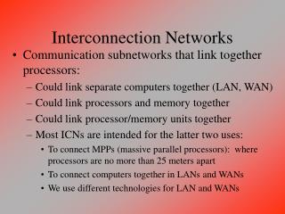
Connecting / Interconnection Structures • All the units must be connected • Different type of connection for different type of unit • Memory • consists of N words of equal length. • A word of data can be read from or written into the memory. • Location for operation specified by an address. • I/O • Functionality similar to memory • 2 operations: Read and Write • May control more than one external device • CPU • Reads in instruction and data, writes out data after processing, and uses control signals to control overall operation of the system • Also receives interrupt signal
Computer Modules • Memory to Processor • - Processor reads instruction/a unit of data from memory • Processor to Memory • - Processor writes a unit of data to memory • I/O to Processor • Reads data from an I/O device via an I/O module • Processor to I/O • Processor sends data to I/O devices • I/O to/from Memory • I/O modules is allowed to exchange data directly with memory, w/out going thru CPU, using DMA • *** Most common interconnection structures is the BUS and various multiple-bus structures
Memory Connection • Receives and sends data • Receives addresses (of locations) • Receives control signals • Read • Write • Timing
Input/Output Connection(1) • Similar to memory from computer’s viewpoint • Output • Receive data from computer • Send data to peripheral • Input • Receive data from peripheral • Send data to computer
Input/Output Connection(2) • Receive control signals from computer • Send control signals to peripherals • e.g. spin disk • Receive addresses from computer • e.g. port number to identify peripheral • Send interrupt signals (control)
CPU Connection • Reads instruction and data • Writes out data (after processing) • Sends control signals to other units • Receives (& acts on) interrupts
Buses • There are a number of possible interconnection systems • Single and multiple BUS structures are most common • e.g. Control/Address/Data bus (PC) • e.g. Unibus (DEC-PDP)
What is a Bus? • Bus is a group of lines that serves as a connecting path for several devices. In addition to the lines that carry the data , the bus must have the lines for address and control purposes. • A communication pathway connecting two or more devices • Usually broadcast • Often grouped • A number of channels in one bus • e.g. 32 bit data bus is 32 separate single bit channels • Power lines may not be shown
Data Bus • Carries data • Remember that there is no difference between “data” and “instruction” at this level • Width is a key determinant of performance • 8, 16, 32, 64 bit
Address bus • Identify the source or destination of data • e.g. CPU needs to read an instruction (data) from a given location in memory • Bus width determines maximum memory capacity of system • e.g. 8080 has 16 bit address bus giving 64k address space
Control Bus • Control and timing information • Memory read/write signal • Interrupt request • Clock signals
Bus Interconnection Scheme • Data lines • provide a path for moving data among system modules. • Called data bus. May consists of 32,64, 128 or even more • Number of lines – width • 1 line can carry only 1 bit, so number of lines determine how many bits can be transferred at a time • Width of data bus is a key factor in determining overall system performances
Bus Interconnection Scheme • Address lines • Used to designate the source/destination of the data on the data bus. • Generally also used to address I/O ports • Control Lines • Used to control the access to and the use of the data and address lines. • Data and address lines are shared by all components, there must be a means of controlling their use. • Control signals submit both command and timing infos among system modules
Big and Yellow? • What do buses look like? • Parallel lines on circuit boards • Ribbon cables • Strip connectors on mother boards • e.g. PCI • Sets of wires • Operation of the bus • Send data: • Obtain the use of the bus • Transfer data via the bus • Request data: • Obtain the use of data • Transfer a request to the other module over appropriate control and address lines.
Physical Realization of Bus Architecture • A number of parallel electric conductor. • Classic bus: metal lines etched in a card or PCB • Extends across all of the system components, each of which taps into some or all of the bus lines • Modern system tend to have all of the major components on the same board with more elements on the same chip as the processor • On chip bus may connect the processor and cache memory • On board bus may connect processor to main memory and other components
Single Bus Problems • Lots of devices on one bus leads to: • Propagation delays (much more time taken) • Long data paths mean that co-ordination of bus use can adversely affect performance • If aggregate data transfer approaches bus capacity (bottleneck) • Most systems use multiple buses to overcome these problems
Traditional (ISA)(with cache) • Reasonably efficient but begin to break down as higher and higher is seen in I/O devices.
High Performance Bus • Cache controller integrated in a bridge, or buffering device that connects to the high speed bus • Advantage: the high speed bus brings high demand devices into closer integration with the processor and at the same time is independent of the processor.
Bus Types • Dedicated • Separate data & address lines • Multiplexed • Shared lines • Address valid or data valid control line • Advantage - fewer lines • Disadvantages • More complex control • Ultimate performance
Bus Arbitration • It is process by which the next device to become the bus master is selected and bus mastership is transferred to it. Two ways for doing this: centralised or distributed. • More than one module controlling the bus • e.g. CPU and DMA controller • Only one module may control bus at one time
A simple arrangement for bus arbitration using a daisy chain
Centralised or Distributed Arbitration • Centralised • Single hardware device controlling bus access • Bus Controller • Arbiter • May be part of CPU or separate • Distributed • Each module may claim the bus • Control logic on all modules
Centralised or Distributed Arbitration • Distributed • Each module may claim the bus • Control logic on all modules
Timing • Co-ordination of events on bus • Synchronous or asynchronous timings • Synchronous • Events determined by clock signals • Control Bus includes clock line • A single 1-0 is a bus cycle • All devices can read clock line • Usually sync on leading edge • Usually a single cycle for an event
Synchronous Timing Diagram • Occurrence of events determined by a clock • All devices on the bus can read a clock line • All events start at the beginning of a clock cycle • Most events occupy a single clock cycle. • The processor places a memory address on the address lines during 1st clock cycle • Once stabilized, processor issues address enable signal.
Synchronous Timing Diagram • READ operation: • processor issues read command at the start of 2nd cycle. • memory module recognizes the address, after delay 1cycle then place data on data line. • Processor reads data from data lines and drop a read signal WRITE operation: Processor puts the data on the data lines at the start of 2nd clock cycle, and issue write command after data lines have stabilized. Memory copies information from data lines during 3rd clock cycle