Download

1 / 148
1.51k likes | 1.79k Views
Chapter 7 THERMOELECTRIC THERMOMETRY. Thomson refers to this as the specific heat of electricity because of an apparent analogy between and the usual specific heat c of thermodynamics.

E N D
Thomson refers to this as the specific heat of electricity because of an apparent analogy between and the usual specific heat c of thermodynamics. Note that represents the rate at which heat is absorbed , or evolved , per unit temperature difference per unit current , whereas c represents the heat transfer per unit temperature difference per unit mass . The Thomson coefficient is also seen to represent an emf per unit difference in temperature. Thus the total Thomson voltage set up in a single conductor may be expressed as
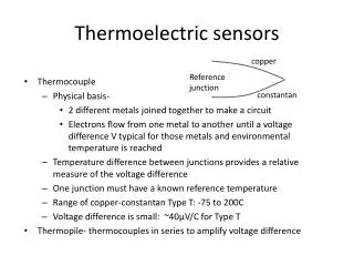
7.1 Historical Development of Basic Relations Thomas Johann Seebeck , the German physicist , discovered in 1821 the existence of thermoelectric currents while observing electromagnetic effects associated with bismuth-copper and bismuth-antimony circuits [1],[2]. His experiments showed that , when the junctions of two dissimilar metals forming a closed circuit are exposed to different temperatures , a net thermal electromotive force is generated that induces a continuous electric current .
The Seebeck effect concerns the net conversion of thermal energy into electrical energy with the appearance of an electric current. The Seebeck voltage refers to the net thermal electromotive force set up in a thermocouple under zero-current conditions. The direction and magnitude of the Seebeck voltage E, depend on the temperatures of the junctions and on the materials making up the thermocouple. For a particular combination of materials, A and B, and for a small temperature difference, dt, the Seebeck voltage may be written (7.1)
where αA,Bis a coefficient of proportionality called the Seebeck coefficient. (This is commonly called the thermoelectric power). Thus the Seebeck coefficient represents, for a given material combination, the net change in thermal emf caused by a unit temperature difference; that is , (7.2)
Thus if determined by calibration, then . Note that, based on the validity of the experimental relation, (7.11) where t1 < t2 < t , It follows that is entirely independent of the reference temperature employed . In other words, for a given combination of materials, the Seebeck coefficient is a function of temperature level only.
Jean Charles Athanase Peltier, the French physicist, discovered in 1834 peculiar thermal effects when he introduced small, external electric currents in Seebeck’s bismuth- antimony thermocouple . His experiments show that when a small electric current is passed across the junction of two dissimilar metals in one direction, the junction is cooled (i.e., it acts as a heat sink) and thus absorbs heat from its surroundings. When the direction of the current is reversed, the junction is heated (i.e., it acts as a heat source) and thus releases heat to its surroundings.
The Peltier effect concerns the reversible evolution, or absorption, of heat that usually takes place when an electric current crosses a junction between two dissimilar metals. (In certain combinations of metals, at certain temperatures, there are thermoelectric neutral points where no Peltier effect is apparent). This Peltier effect takes place whether the current is introduced externally or is induced by the thermocouple itself. The Peltier heat was early found to be proportional to the current and may be written (7.12)
Where л is a coefficient of proportionality known as the Peltier coefficient or the Peltier voltage. Note thatлrepresents the reversible heat that is absorbed, or evolved, at the junction when unit current passes across the junction in unit time, and that it has the dimensions of voltage. The direction and magnitude of the Peltier voltage depend on the temperature of the junction and on the materials making up the junction ; however,лat one junction is independent of the temperature of the other junction .
External heating, or cooling, of the junctions results in the converse of the Peltier effect. Even in the absence of all other thermoelectric effects, when the temperature of one junction (the reference junction) is held constant and the temperature of the other junction is increased by external heating , a net electric current will be induced in one direction . If the temperature of the latter junction is reduced below the reference junction temperature by external cooling, the direction of the electric current will be reversed. Thus the Peltier effect is seen to be closely related to the Seebeck effect.
Peltier himself observed that, for a given electric current, the rate of absorption, or liberation, of heat at a thermoelectric junction depends on the Seebeck coefficient a of the two materials. Note that the Peltier thermal effects build up a potential difference that opposes the thermoelectric current, thus negating the perpetual-motion question. William Thomson (Lord Kelvin), the English physicist, came to the remarkable conclusion in 1851 that an electric current produces different thermal effects, depending on the direction of its passage from hot to cold, or from cold to hot, in the same metal.
By applying the (then) new principles of thermodynamics to the thermocouple and by disregarding (with tongue-in-cheek) the irreversible and conduction-heating processes, Thomson reasoned that, if an electric current produced only the reversible Peltier heating effects, the net Peltier voltage would equal the Seebeck voltage and would be linearly proportional to the temperature difference at the junctions of the thermocouple .
This reasoning led to requirements at variance with observed characteristics (i.e., dEs/dt constant). Therefore, Thomson concluded that the net Peltier voltage was not the only source of emf in a thermocouple circuit but that the single conductor itself, whenever it is exposed to a longitudinal temperature gradient, must also be a seat of emf. A. C. Becquerel had at that time already discovered a thermoelectric neutral point, that is, Es = 0, for an iron-copper couple at 280℃. Thomson agreed with Becquerel’s conclusion and started his thermodynamic reasoning from there.
The Thomson effect concerns the reversible evolution, or absorption, of heat occurring whenever an electric current traverses a single homogeneous conductor, across which a temperature gradient is maintained, regardless of external introduction of the current or its induction by the thermocouple itself. The Thomson heat absorbed, or generated, in a unit volume of a conductor is proportional to the temperature difference and to the current; that is, where σ is a coefficient of proportionality called the Thomson coefficient. (7.13)
where its direction and magnitude depend on temperature level, temperature difference, and material considered. Note that the Thomson voltage alone cannot sustain a current in a single homogeneous conductor forming a closed circuit, since equal and opposite emfs will be set up in the two paths from heated to cooled parts. (7.14)
Soon after his heuristic reasoning, Thomson succeeded in demonstrating indirectly the existence of the predicted Thomson emfs (see Figure 7. 1). He sent an external electric current through a closed circuit formed of a single homogeneous conductor that was subjected to a temperature gradient and found the heat to be slightly augmented or diminished by the reversible Thomson heat in the paths from
Figure7.1 Thomson experiment to demonstrate existence of reversible emfs in a single conductor. (1) Points A and B can be found, when the switch is open, having the same temperature. (2)When an electric current is passed through the copper bar, point A becomes cooler while point B becomes hotter. (3) That is, Joule heating is slightly affected by the reversible Thomson emf , which either opposes or adds to the external emf when the copper bar is preferentially heated.
(4) Thomson concluded that hot copper was electrically positive with respect to cold copper, cold to hot or from hot to cold, depending on the direction of the current and the material under test. In summary, thermoelectric currents may exist whenever the junctions of a circuit formed of at least two dissimilar materials are exposed to different temperatures. This temperature difference is always accompanied by irreversible Fourier heat conduction; The passage of electric currents is always accompanied by irreversible Joule heating effects.
At the same time, the passage of electric currents is always accompanied by reversible Peltier heating or cooling effects at the junctions of the dissimilar metals; The combined temperature difference and passage of electric current is always accompanied by reversible Thomson heating or cooling effects along the conductors. The two reversible heating-cooling effects are manifestations of four distinct emfs that make up the net Seebeck emf: where the three coefficients, α,π,σ are related by the Kelvin relations. (7.17)
7.2 The Kelvin Relations Assuming that the irreversible and heat-conduction effects can be completely disregarded (actually, they can only be minimized, since, if thermal conductivity is decreased , electrical resistivity usually is increased, and vice versa , see Figure 7.2) , the net rate of absorption of heat required by the thermocouple to maintain equilibrium in the presence of an electric current is (7.15)
This is in accord with the first law of thermodynamics, according to which heat and work are mutually convertible. Thus the net heat absorbed must equal the electric work accomplished or, in terms of a unit charge of electricity, must equal the Seebeck emf Es, which may be expressed in the differential form (7.16)
The second law of thermodynamics may also be applied to the thermocouple cycle (the unit charge of electricity again being considered) as where ΔQ represents the various components of the net heat absorbed (i.e., the components of Es), and Tabsolute is the temperature at which the heat is transferred across the system boundaries. (7.18)
Equation 7.10 can be expressed in the differential form Combining the differential expressions for the first and second laws of thermodynamics, we obtain the Kelvin relations from which we can determine, α,π,Δσ , when Es is obtained as a function of T. (7.19) (7.20) (7.21)
is taken to represent the thermoelectric characteristic of a thermocouple whose reference junction is maintained at 0℃ in which the coefficients a and b are obtained, for example , by the curve fitting of calibration data , then An example of the use of these coefficients is given in Figure 7.3. (7.22) (7.23) (7.24) (7.25)
Given the two constants, a and b, as determined with respect to platinum, By way of illustration, consider the following combinations of materials: iron-copper and iron-constantan, with their measuring junctions at 200℃ and their reference junctions at 0℃:
Since Seebeck voltage Figure 7.3 Determination of various thermoelectric quantities applied to thermocouples
Note how different combinations of materials give widely different thermal emfs. Now we proceed to write expressions for α,πand Δσ to note how the separate emfs combine to give the ( net ) Seebeck emf. Since Seebeck coefficient,
Note that it is the great difference in Seebeck coefficients (thermoelectric powers) for the two combinations that accounts for the difference in thermal emfs: Since =Peltier coefficient =Peltier voltage
Note that, in the case of the iron-copper ( I-Cu ) couple, , where as in the more usual I-C couple, .
Since=Thomson coefficient , and = Thomson coefficient Figure 7.3 continued
These figures, of course, check with the original calculations. Note that, in the I-Cu case, the net Thomson emf far outweighs in importance the net Peltier emf, whereas in the I-C case , the converse is true . Figure 7.3 (concluded)
7. 3 Microscopic Viewpoint of Thermoelectricity What gives rise to these thermoelectric effects ? Recall from your chemistry that when the loosely bound outer (valence) electrons of a material absorb enough energy from external sources, they may become essentially free from the influence of their nuclei. Once free, these electrons can absorb any amount of energy supplied to them, and it is usual to suppose that the free electrons in a metal act collectively as an idealized gas (see Chapter2)。 Even at a common temperature, however, the energies and densities of the free electrons in different materials need not be the same.
Thus when two different materials in thermal equilibrium with each other are brought in contact, there usually will be a tendency for electrons to diffuse across the interface. The electric potential of the material accepting electrons would become more negative at the interface, whereas that of the material emitting electrons would become more positive. In other words, an electric field would be set up by the electron displacement that opposes the osmotic process. When the difference in potential across the interface just balances the thermoelectric (diffusion) force, equilibrium with respect to a transfer of electrons would be established.
If two different homogeneous materials are formed into a closed circuit and the two junctions are maintained at the same temperature, the resultant electric fields would exactly oppose each other, and there would be no net electron flow. However, if these two junctions are maintained at different temperatures , a net diffusion current will be induced in coincidence with a net electric field (the random motion of the free electrons is on the average in the direction of the net potential gradient , and this gives rise to the electric current).
From conservation principles, the power to drive this electric current could only come from a net absorption of thermal energy from the surroundings by the free electrons of the materials, since there is no observable change in the nature or composition of the thermoelectric materials. But what accounts for this net absorption of heat? Why does the thermocouple act as a heat engine (i.e., a device that makes available as work some portion of the thermal energy acquired from a source)?
Consider first a closed circuit of a single material (thus avoiding for a time the thermoelectric effects). Under the influence of a temperature gradient alone, the material will conduct a thermal current. But all the thermal energy absorbed by the circuit at one zone is rejected by the circuit at another zone. Thus the Fourier effect exhibits no accumulation of heat in the steady state, and cannot account for a thermally induced electric current in a thermocouple circuit. Again, under the influence of a voltage gradient alone, this same single material closed circuit will con- duct an electric current.
But the only thermal effect associated with this current is the inevitable heat generation. Thus the Joule effect exhibits no absorption of heat from outside the circuit and cannot account for a thermally induced electric current in a thermocouple circuit. Evidently, when examining the mechanism by which a closed circuit formed of two unlike materials acts as a heat engine, we need concern ourselves only with the reversible thermoelectric effects. (Perhaps similar reasoning guided Thomson when he successfully obtained the valid Thomson relations by intuitively disregarding the irreversible Joule and Fourier processes.)
From this viewpoint, the resultant electric current in the thermocouple circuit having its junctions maintained at different temperatures agrees in direction with the natural (Peltier) potential gradient at the hot junction , and thus tends to wipe out ( do away with the need for ) this field . At the cold junction, this same thermally induced current must cross the interface against the natural potential gradient, and this tends to build up a stronger field of opposition there.
In terms of the idealized gas, the free electrons expand isothermally across the hot junction interface because the flow is in the direction of the Peltier potential gradient there. This expansion tends to cool the hot junction but, in face of the isothermal restriction and in accord with the first law of thermodynamics, the hot junction absorbs just enough heat from its surroundings to maintain its temperature.
These Peltier (junction) effects, although usually predominating, do not tell the complete story. As Thomson first pointed out, there will be thermoelectric heating effects along each of the materials making up the circuit whenever an electric current and a temperature gradient exist. The Thomson effect may be visualized as follows. If a single conductor is preferentially heated, electrons usually tend to leave the hot end more frequently than the cold. Just as we found at the junctions, an opposing electric field would be set up along the single conductor by this diffusion of electrons.
Thus whenever an electric current occurs in a closed thermocouple circuit, it must either agree with or oppose these Thomson (material) potential gradients, and this accounts for heating and cooling effects in addition to the Peltier (junction) effects discussed previously. Hence the thermocouple in a temperature gradient does qualify as a heat engine in that there will always be a net absorption of heat from its surroundings per unit time , and we see once more that it is just this excess of thermal power arising entirely from reversible thermoelectric effects that sustains the thermoelectric current in the circuit .
7 .4 Macroscopic Viewpoint of Thermoelectricity The historical viewpoint presented thus far has avoided the real irreversible I2R and heat conduction effects in order to arrive at the useful and experimentally confirmed Kelvin relations. We now discuss how the present-day irreversible thermodynamic viewpoint removes this flaw in our reasoning.
Basically, we judge whether a given process is reversible or irreversible by noting the change in entropy accompanying a given change in the thermodynamic state. Thus, if , we say the process is irreversible ; or , stated in a more useful manner , (7.26) or (7.27)
Hence only in the absence of entropy within the system boundaries do we have the reversible case, , which may be handled adequately by classical thermodynamics in the steady and quasi-steady states . Evidently the rate of production of entropy per unit volumeξis an important quantity in irreversible thermodynamics . It may be expressed as where Adx is the area times the differential length. (7.28)
Another significant quantity, the product Tabsolute(called the dissipation) , can always be split either into two terms or into a sum of two terms , one associated with a flow J, and the other associated with a force X.
Furthermore, in many simple cases a linear relation is found (by experiment) to exist between the flow and force terms so defined; for example, in the one- dimensional, isothermal, steady flow of electric charges, , across a potential gradient-dE/dx , it may be shown that (7.29)