Download
1 / 59
600 likes | 762 Views
Introduction to Long-Throated Flumes and Broad-Crested Weirs. The term long-throated flume describes a broad class of critical-flow flumes and broad-crested weir devices used to measure flow in open channels. Critical-Flow Measurement Devices. Flumes, sharp-crested weirs, broad-crested weirs

E N D
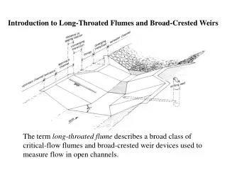
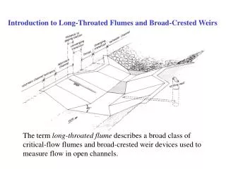
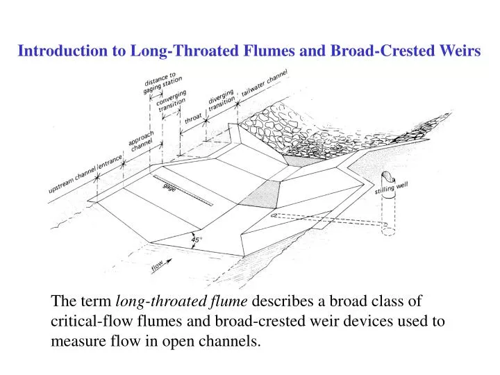
Introduction to Long-Throated Flumes and Broad-Crested Weirs The term long-throated flume describes a broad class of critical-flow flumes and broad-crested weir devices used to measure flow in open channels.
Critical-Flow Measurement Devices • Flumes, sharp-crested weirs, broad-crested weirs • Produce critical-depth flow in a control section • Froude number = V/(gD)1/2=1 • Critical depth occurs at locations where the downstream depth does not “hold the flow back” • Minimum specific energy for a given flow • Maximum flow for a given specific energy • Shallow-water waves cannot travel upstream • Tailwater does not affect headwater elevation • Flow rate through the critical section is a function of the upstream head, acceleration of gravity, and the control section size
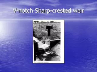
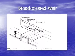
Traditional Critical-Flow Devices • Most critical-flow devices have curvilinear,three-dimensional flow fields in the control section • All such devices require laboratory calibration • Flumes • Parshall flumes, cutthroat flumes, H-flumes, etc. • Sharp-Crested Weirs • V-notch weirs, Cipoletti weirs, contracted and suppressed rectangular weirs, etc. • Broad-Crested Weirs • If they do not have a streamlined approach
Long-Throated Flumesand Broad-Crested Weirs • Long-throated flumes with a streamlined converging transition have one-dimensional flow in the control section -- Long-throated means long enough to eliminate lateral and vertical contraction of the flow at the control section…streamlines are essentially parallel • Can be calibrated using well-established hydraulic theory • No laboratory testing needed • Calculations are iterative, but computer models that do the calculations have made long-throated flumes reasonable to implement in recent years
Developing Rating Tables First, relate Q to yc as follows: • Guess a value of yc • Compute area, Ac, and top width, Bc, at critical section • Compute Q, and compute Hc
Developing Rating Tables Next, relate h1 to yc • Assume H1≈Hc • Solve iteratively for h1 using energy equation • Compute losses from 1 to c and revise: H1 = Hc+DH1 • Repeat until solution converges. We know H1 versus Q for a given value of yc.
Developing Rating Tables • Procedure as described yields Q and h1 values at specified increments of yc (irregular values of Q and h1) • Similar techniques can solve for Q at specified h1 or h1 at specified Q • Knowing Hc, we can also solve for H2 (highest allowable downstream tailwater) by subtracting DH2, the loss caused by expanding transition and exit channel friction
Submergence of Flumes and Weirs • h2/h1 or hb/ha is thesubmergence ratio • Sharp-crested weirs • NO SUBMERGENCEALLOWED • Parshall flume • Some submergence allowed • Long-throated flume • Most submergence allowed
Submergence of Parshall and Other Short-Throated Flumes • Some submergence allowed • Modular limit varies with flume size (50-80 percent) • Submergence correction needed when above modular limit (no longer a true critical-flow device)…even with correction, accuracy suffers, especially above 90 percent submergence
Submergence of Long-Throated Flumes and Broad-Crested Weirs • Location of critical section upstream from expanding transition makes it difficult to submerge the control section. • Gradual expansion (downstream ramp) can recover kinetic energy from control section • Highest modular limit (lowest head loss) of any critical-flow device • Modular limit varies, but can be predicted using WinFlume • Typically 80-90+ percent • No submergence correction needed as long as submergence is less than modular limit • Flow rate is always a function of ONLY the upstream water level
Long-throated flumes are the measurement device of choice for many applications. Advantages include: • Rating tables with error of less than 2% in the computed discharge can be computed for any combination of prismatic control section and an arbitrarily shaped approach channel • If the throat is horizontal in the direction parallel to the flow, accurate rating tables can be computed using as-built dimensions • Throat can be any shape in the direction perpendicular to the flow, allowing the complete range of discharges to be measured with good precision • Required head loss across the flumes is minimal (modular limit is high) • Long-throated flumes can be operated in free-flow with greater submergence than all other critical-flow devices, and the submergence limit (modular limit) and the associated head loss requirement can be determined using the WinFlume program • With properly constructed gradual converging transition, there is virtually no problem passing floating debris • Can be designed to pass sediment transported by channels having subcritical flow • Economical to construct • Very adaptable to installation in existing canals
Principal Design Issues • Site • Uniform, fully-developed flow conditions approaching structure so that hydraulic theory is applicable • Flume control section • Ensure that flume is not submerged by tailwater (contraction must be enough to force critical depth) • Ensure structure ponds water deep enough to stabilize upstream water surface for accurate measurement • Ensure that flume does not create a “lack of freeboard” problem • Ensure that contraction produces enough head to make an accurate flow measurement • Component lengths must meet “long-throated” criteria
Lengths of Flume Components • Throat section length, L 0.07<H1/L<0.7 for ±2% uncertainty 0.05<H1/L<1.0 for ±4% uncertainty • Floor and sidewalls of converging transition 2.5 to 4.5:1 transition slope • Diverging transition No flatter than 10:1 • Gaging station location (approach channel length) > H1 upstream of start of converging transition (2 to 3) * H1max from start of throat
Constructability Range of Flows to be Measured Throat Section Shape Selection
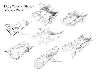
Typical Flume/Weir Configurations • Sill in a concrete-lined canal • Rectangular-throated flumes for earthen canals • Triangular-throated flumes for natural channels • Flumes in circular pipes • Portable and temporary flumes
Poor construction detail. Abrupt changein channel cross section between gage and critical section.
Flume Design & Selection • Pre-computed flume designs can be chosen using tables in the Water Measurement Manual • Designs can be developed using the WinFlume computer program • Allows for customization • Provides best rating table accuracy • Simplifies checking of design
Water Resources Research Laboratory Denver, Colorado U.S. Water Conservation Laboratory Phoenix, Arizona International Institute for Land Reclamation & Improvement Wageningen, The Netherlands WinFlumeSOFTWARE FOR THE DESIGN AND CALIBRATION OF LONG-THROATED FLUMES AND BROAD-CRESTED WEIRS
Evolution of Long-Throated Flume Design Software • Batch oriented FORTRAN codes developed by ARS at U.S. Water Conservation Laboratory, Phoenix. • Interactive program written in Clipper for DOS-based computers, available since early 1990’s (FLUME 3.0). Joint effort of ARS and ILRI. • WinFlume program written in Visual Basic for Windows 95/NT environment. This is an upgrade of FLUME 3.0, and is a joint effort of Reclamation and ARS, with programming work being performed by Reclamation.
New Output Features • Full-scale plotted wall gauges • Can be provided to fabricator for construction of durable wall gauges graduated in head or discharge units, adjusted for installation on sloped canal bank • On-screen preview of finished wall gauge • Plotted continuously on roll-feed plotters, or in sections with match marks on page-type printers (e.g. laser printers) • Ditchrider’s rating table • Alternative equation forms in curve-fitting module:
Calibrating an Existing Structure • Define geometry of canal and flume • Provide hydraulic data and other properties • Construction material • Tailwater conditions • Generate output • Rating tables and curves • Curve-fit equation for data logger • Wall gage data and/or plot
Designing a New Structure • Define canal geometry and initial flume control section shape • Provide hydraulic data, canal/flume properties, design requirements • Construction material • Tailwater conditions • Water level measurement method and required flow measurement accuracy • Required freeboard in upstream channel • Evaluate designs and choose final design • Generate output
Control Section Adjustment Methods Raise sill height Raise entire throat section Raise inner section of throat (used with complex cross-sections) Adjust lateral contraction by changing bottom width of throat section or changing diameter or focal distance of circular or parabolic sections (only option for movable-crest flumes) Head Loss Objectives Minimum head loss Maximum head loss Intermediate head loss Match head loss to drop in canal invert at site Design Criteria, Methods, Objectives • Primary Design Criteria (4) • Maintain necessary freeboard at maximum flow • Maintain modular (critical) flow at minimum and maximum flow (ensure free flow) • Froude number at maximum flow must be less than 0.5 • Secondary Design Criteria (2) • Control section must produce sufficient head to provide a user-specified level of discharge-measurement precisionat both minimum and maximum flow, based on the precision of the device used to measure upstream water level.
HOW TO OBTAIN WINFLUME • The WinFlume program is available on the World Wide Web at: http://www.usbr.gov/pmts/hydraulics_lab/winflume • There are 16-bit and 32-bit versions available that are appropriate for Windows 3.1x, Windows 95, Windows 98, and Windows NT systems. This work has been funded by the U.S. Bureau of Reclamation’s Water Conservation Field Services Program.