Download
1 / 27
270 likes | 364 Views
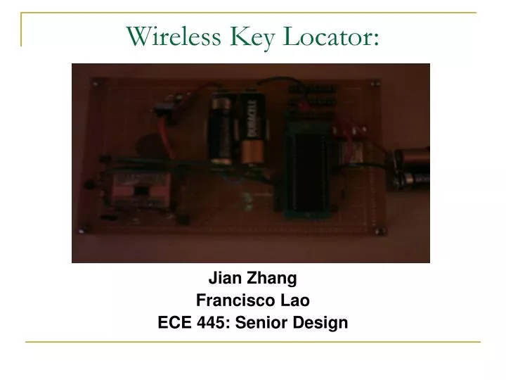
Wireless Key Locator:. Jian Zhang Francisco Lao ECE 445: Senior Design. Objectives:. To keep track of one’s possessions such that one will never lose/misplace important items, such as keys, wallets, PDAs, etc. Similar Available Products. “Remote Control” Finder

E N D
Wireless Key Locator: Jian Zhang Francisco Lao ECE 445: Senior Design
Objectives: • To keep track of one’s possessions such that one will never lose/misplace important items, such as keys, wallets, PDAs, etc.
Similar Available Products • “Remote Control” Finder • Radio frequency remote controller locators • Sound induced remote controller locators
Problems • Radio Frequency Finder • Uses one remote to find another • High power consumption • Sound-induced Finder • Environmentally limited • Very limited range
Our Solution • RFid • Radio Frequency IDentification • RFID couples data into the RF portion of the electromagnetic spectrum • An RFID system consists of • Transponder • Transceiver • Antenna
RFID Pros and Cons: • Pros • Power efficient • Very portable • Cheap • Long lifetime • Cons • Many different protocol standards • Operative range proportional to tag size and reader power • Operation range affected by environment
Applications of RFid Today: • Inventory control • Product tracking through manufacturing and assembly • ID badges and assess control • Parking lot assess and control
Our Design Goals • Low Power Consumption • Cheap • Portable • ~6 ft. Range
Power Regulator • Goals: • Step down from 6V to 5V efficiently • Provide stable output independent of load • Results: • From Scope
Transceiver • Goals: • Low Power Consumption • ~ 6 ft. operation range • Small • Resolution: • TI-S6700 Transceiver IC • Small • Cheap ($10 per IC) • Low power consumption • 50 uA Idle-Oscillator off • 15 mA Idle-Oscillator On • High power transmission • 200 mA
Transceiver Schematic Transceiver Design from TI-S6700 Manuel
Microcontroller • Goals: • Provides appropriate inputs to the transceiver and the LEDs • Decodes transceiver outputs • Resolution: • PIC16F877
Transponders: • Goals • Cheap • Portable • No External Power Source • Resolutions • Ti Tag-It Transponders
Success and Failure • Success • Power Regulator Works Properly • Current drawn under no-load condition ~ 0.001 A • Voltage Output: 5.054 V, ripple 8.44 mV • Microcontroller Outputs and decodes properly • Transceiver Outputs Properly • Failure • Tag will not respond properly to Transceiver
Experimental Results: Transceiver • Output Data of Transceiver using Tag-It
Experimental Result: Tag + Transceiver • Transceiver with Tag • Transceiver without Tag
Power Consumption • Direct Mode: • PIC + Transceiver Transmit mode 198 mA PIC 23 mA Transceiver 175 mA • PIC + Transceiver Idle mode 52 mA PIC 23 mA Transceiver 29 mA PIC + Transceiver Idle mode + Regulator ~56 mA
Power Consumption • Tag-it Mode • PIC + Transceiver Transmit mode 215 mA PIC 29 mA Transceiver 186 mA • PIC + Transceiver Idle mode 59 mA PIC 29 mA Transceiver 30 mA PIC + Transceiver Idle mode + Regulator ~65 mA
Power Consumption: • Idle state oscillator OFF: (NO XTAL) • Direct Mode: • PIC + Transceiver Transmit mode 35 mA PIC 23 mA Transceiver ~12 mA • Tag-It Mode: • PIC + Transceiver Transmit mode 39 mA PIC 28 mA Transceiver ~11 mA
Problem Areas: • Incorrect RFid tag response • Power consumption not suitable for battery use
Our Explanations: • Tag Response: • Incorrect CRC of transmission sequence • Frequency mismatch • Power Consumption: • Increased LOAD due to passive components
Future Works • Smaller, more power efficient microcontroller • Small, stable, rechargeable source • Long range tags that respond to multiple transmission protocols • Design high-performance planar antenna on transceiver circuit
Acknowledgements • Jim Wehmer and the Part Shop people • Richard Cantzler • Chirantan Mukophadyay • Tech. Support at TI