Download
1 / 41

E N D
HARD DISK Drive Concepts In principle, a hard-disk drive is very similar to a floppy drive—a magnetic recording media is fixed on the (spindle) motor, which is then spun at a high rate of speed. Magnetic read/write heads in close proximity to the media can step rapidly across the revolving media to sense or create flux transitions, as required. When one looks closely, however, one can see that there are some major physical differences between floppy and hard drives.
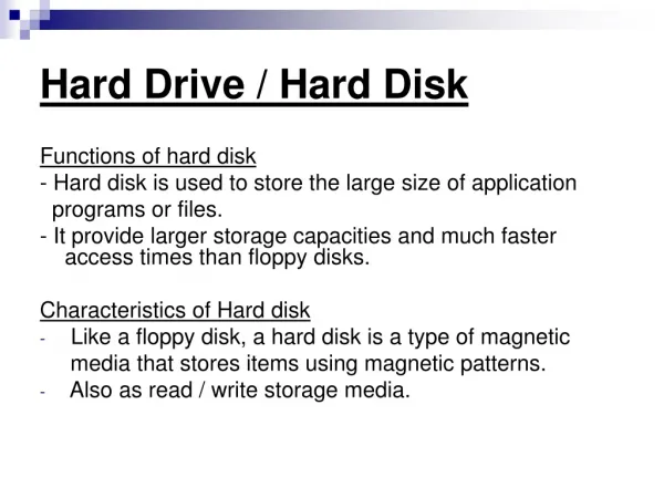
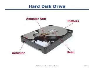
HARD DISK Hard drives use rugged, solid substrates, called platters. One can clearly see the platters of a hard drive in figure shown. A platter is traditionally made of aluminum because aluminum is a light
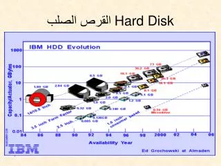
HARD DISK material, hence it is easy to machine the desired tolerances, and it holds its shape under the high centrifugal forces that occur at high rotation rates. But today, most platters are made from materials like glass or ceramic composites, which have very low thermal expansion rates. As the major advantage of a hard drive is speed, platters are rotated from about 7600 RPM to as much as 10,000 RPM (compared to older hard drives, which ran at 3600 to 5200 RPM). A hard drive commonly uses two or more platters, although extremely small drive assemblies might use a single platter. Hard drives must be capable of huge recording densities—well over 10,000
HARD DISK AIR FLOW and HEAD FLIGHT The heads could be mechanically fixed, but fixed-altitude flight does not allow for shock or natural vibration that is always present in a drive assembly. Instead, R/W heads are made to float within microinches of a platter surface by suspending the heads on a layer of moving air. Disk (platter) rotation creates a slight air cushion that keeps the head slightly above the platter surface. one might also observe that some air is passed through a fine air filter that helps to remove any particles from the drive’s enclosure. It is important that all hard drives seal their platter assemblies into an air-tight chamber. The reason for such a seal is to prevent dust, dirt, spills, or strands of hair from entering into drive. These particles that lands on a platter’s surface can easily result in a head crash. A head crash can damage the head, the media, or both—and render the head and platter unusable.
HARD DISK Latency A finite period of delay occurs between the moment that a read or write command is initiated over the drive’s physical interface and the moment that desired information is available (or placed). This delay is known as latency. More specifically, latency refers to the time it takes for needed bytes to pass under a R/W head. If the head has just missed the desired location, the head must wait almost a full rotation before the needed bits are available again, so latency can be rather long. In general, a disk drive is specified with average latency, which (statistically) is time for the spindle to make half of a full rotation. For a disk rotating at 3600 RPM (60 rotations per second), a full rotation is completed in (1/60) = 16.7 ms. Average latency would then be (16.7/2) = 8.3 ms. Disks spinning at 5200 RPM offer an average latency of 5.8 ms, etc. As a rule, the faster a disk spins, the lower its latency will be. Ultimately, disk speed is limited by centrifugal forces acting on the platters.
HARD DISK Tracks, Sectors, and Cylinders As with floppy drives, one cannot simply place data anywhere on a hard-drive platter—the drive would have no idea where to look for data, or if the data is even valid. A drive can move its R/W heads over the spinning media to locate needed data or programs in a matter of milliseconds. Every concentric circle on a platter is known as a track. A current platter generally contains 2048 to more than 16278 tracks. Because each track is located directly over the same tracks on subsequent platters, each track in a platter assembly can be visualized as a “cylinder” that passes through every platter. The number of cylinders is equal to the number of tracks on one side of a platter. Once a R/W head finishes reading one track, the head must be stepped to another (usually adjacent) track. This stepping process, no matter how rapid, does require some finite amount of time. This is called seek time and it is often less than 1 ms for track-to-track seeks. When the head tries to step directly from the end of one track to the beginning of another, the head will arrive too late to catch the new track’s index pulse(s), so the drive will have to wait almost an entire rotation to synchronize with the track index pulse. By offsetting the start points of each track, head travel time can be compensated for. This cylinder-skewing technique is intended to improve hard-drive performance by reducing the disk time lost during normal head steps. A head should be able to identify and read the desired information from a track within one disk rotation.
HARD DISK • Recoding Methods • Three methods have been employed in recording the data on a hard disk. They are: • FM -Frequency Modulation (was used in floppy) • MFM -Modified Frequency Modulation (is being used in floppy and was in earlier hard disks) • RLL -Run Length Limited (is being used in hard disk) • Now a days, only RLL method is being used in hard disk, and MFM in floppy disk. FM is not used because it occupies more space in hard disk comparing with other two recording methods. FM recording is referred to as single density and MFM as double density.
HARD DISK FM Usually a clock is recorded at the beginning of each bit cell. (Maximum one data bit can be recorded in a bit cell). The data is written as a pulse in the middle of a bit cell. In case the data bit is 1, a pulse is recorded otherwise no pulse is recorded on the media. Recording Format
HARD DISK MFM In MFM recording method, no clock pulse is recorded at the beginning of a bit cell. When the data bit is 1, only a single pulse is recorded in the center of a bit cell and no clock recorded. If a data bit is 0 subsequent to a data bit 1 recorded in the previous cell, no pulse is recorded in the particular cell. If two or more 0s are to be recorded subsequently, only a single clock pulse has to be recorded at the beginning of each bit cell (Remember data pulse is recorded in the center of a bit cell). If a data bit 1 is to be recorded in FM method, two pulses are to be recorded in a bit cell. Whereas in MFM only one pulse is recorded in the center and clock pulse is omitted. From the above it is understood that MFM method occupies only half of the disk space used by FM method and increase the data recoding (storing) capacity by two. In other words doubles the density of the disk.
HARD DISK Run-Length Limited (RLL) RLL recording method provides most efficient way to encode data than any other methods. Using MFM reduces the bit cell size down to the same size as the minimum magnetic flip-flop length, but it is possible to do even better if the number of clock signals are cut back even more. How far one can go depends on how steadily the disk turns and how precisely the spacing of the voltage pulses coming out the head coil is timed. The most popular recording method used in hard disk drive is referred to as 2,7 RLL. This process uses no clock signals at all. This deficiency is made up for by recording on the disk patterns that are different from the ones in the data to be stored. If these patterns are chosen correctly, the controller can reverse that process when it is time to read the data.
HARD DISK Shows how to convert Data stream into Magnetic Transitions
HARD DISK Rather than simply translating the each incoming data bit into transitions, the controller scrutinizes and selects a group of bits at a time for encoding. For each group, a specially chosen sequence of transitions and lack of transitions gets stored. In 2,7 RLL the sequences of Ts and 0s must be chosen such that, no matter what the incoming data bit stream, there will always be at least two and never more than seven 0s between any two Ts. Figure 8 shows how to convert a data bit stream into magnetic transitions (Ts) and spaces between them (0s) by using 2,7 RLL encoding. Bit streamMagnetic Transitions and spaces Sequence 11 = T 0 0 0 10 = 0 T 0 0 000 = 0 0 0 T 0 0 011 = 0 0 T 0 0 0 010 = T 0 0 T 0 0 0011 = 0 0 0 0 T 0 0 0 0010 = 0 0 T 0 0 T 0 0
HARD DISK from the above figure, one can see that no sequence has more than three 0's at the end nor more than four 0’s at the beginning. No matter which sequences are put next to each other, then, there will never be more than seven 0’s between successive Ts. Drives attached to Enhanced Small Device Interface (ESDI) and Small Computer System Interface(SCSI). Controllers are sometimes referred to as using enhanced run-length limited (ERLL) data encoding. Actually, they commonly use 2,7 RLL data encoding, but because they record at a higher bit rate, they also put more bytes of data on a track than, is the case with the standard RLL controllers and drives. Advanced Run-Length Limited Some manufacturer exceeds the limits of 2,7 RLL and this scheme allows an even larger ratio of maximum-to-minimum spacing of the magnetic field transitions. This scheme permits one to pack more data- twice the MFM.
HARD DISK Band Stepper A stepper motor is not like conventional motors that spin continuously when power is turned on; rather it moves in steps according to the no. of electric pulses it receives. The stepper motor direction can be reversed with the positive and negative pulses 16. HARD DISK DRIVES A steel band is attached between the stepper motor shaft and R/W heads. As the stepper motor moves one step to the front or back, the heads correspondingly move one cylinder to the front or back An open-loop system is used with stepper motor, to track the cylinders. It does not use feed to place the heads exactly on the right cylinder. In this system, track 0 is used as the reference point. The microcomputers always keep the present track number with reference to the track 0 position. The track information stored on the track can be utilized by software to position the heads on the right track. Due to climatic changes the steel band and platters may expand or contract. In such case the head position does not correspond to the tracks recorded on the platter. This makes impractical to read the data from the tracks. Some time this can be overcome, by allowing hard disk to warm up so that head can correspond to the tracks. By doing low level formatting, new tracks and sectors can be formed, which will correspond to the head positions and the drive can be reused for storing data.