Download
1 / 45
450 likes | 610 Views
Chap 1 – Services in a Converged Network Learning Objectives. Describe how the Cisco Enterprise Composite Model (ECNM) provides integrated services over an Enterprise network. Describe the key WAN technology concepts.

E N D
Chap 1 – Services in a Converged Network Learning Objectives • Describe how the Cisco Enterprise Composite Model (ECNM) provides integrated services over an Enterprise network. • Describe the key WAN technology concepts. • Identify the appropriate WAN technologies to use when matching ECNM best practices with typical enterprise requirements for WAN communications.
Wide Area Networks (WANs) • A data communications network that serves users across a broad geographic area and often uses transmission devices provided by common carriers
Hierarchical Network Model • Distribution layer - Aggregates the wiring closets, using switches to segment workgroups and isolate network problems in a campus environment. Provides policy-based connectivity. • Core layer - A high-speed backbone that is designed to switch packets as fast as possible. Because the core is critical for connectivity, it must provide a high level of availability and adapt to changes very quickly. Access layer - user access to network devices. In a network campus, the access layer generally incorporates switched LAN devices with ports that provide connectivity to workstations and servers.
Enterprise Composite Network Model • Unfortunately, all too often networks grow in a haphazard way as new components are added in response to immediate needs. • Over time, those networks become complex and expensive to manage. Because the network is a mixture of newer and older technologies, it can be difficult to support and maintain.
Enterprise Composite Network Model • Each module has a distinct network infrastructure with services and network applications that extend across the modules.
WAN Layers • Because the WAN is merely a set of interconnections between LAN based routers, there are no services on the WAN. • WAN technologies function at the lower two layers of the OSI reference model.
WAN Physical Layer Interfaces • WAN physical-layer protocols describe how to provide electrical, mechanical, operational, and functional connections for WAN services. The WAN physical layer also describes the interface between the DTE and the DCE.
WAN Datalink Protocols • WANs require data link layer protocols to establish the link across the communication line from the sending to the receiving device.
WAN Frame Encapsulation Flag Address Control Data FCS Flag 01111110 01111110 • Flag – identifies beginning and end of frame, also provides synchronisation • Address – usually a broadcast address on a point-to-point link • Control – used to provide flow & error control • Information – data field, length depends on network type (Frame Relay, X25, etc) • FCS – 2 or 4 Byte, ITU-T CRC
Circuit Switching Circuit path doesn’t change for the duration of the call, and is not shared with other users • Continuous • Exclusive • Temporary
Circuit Switched Networks Sets up dedicated line similar to a phone call. Data connections initiated when needed. Terminated on completion of data transfer. What uses circuit switching? ISDN uses circuit switching. Dial up modems use circuit switching.
Packet Switching Data transfer inherently ‘bursty’. Transmission of ‘bursty’ data over circuit-switched system wasteful of bandwidth. Packet switching specifically developed for transfer of digital data, to improve bandwidth efficiencies.
Packet Switching - Connectionless P5 P1 Packet Switched Node Packet Switched Node P4 P3 P2 P3 P1 P2 Packet Switched Node Packet Switched Node Packet Switched Node P1 P5 P3 P4 P2 Packet Switched Node P5 P4
Datagram Service: Connectionless communication. The datagram is a data packet that is sent over an IP network. The network layer accepts each message as an independent unit and attempts to deliver it. Packets may beout of order. Datagram is fairly primitive, yet may add error and sequence control at the transport layer. Packet Switching - Connectionless
Packet Switching – Connection Orientated P5 Packet Switched Node Packet Switched Node P4 P3 P2 P1 Packet Switched Node Packet Switched Node Packet Switched Node P5 P4 Packet Switched Node P3 P2 P1
Virtual Circuit Service: A direct connection between 2 devices, yet may be circuitous physical route. Connection-orientated (transport layer) - Little or no errors, messages delivered in same order as supplied. User defines destination, virtual circuit is set up, messages are sent and the circuit is closed. Packet Switching – Connection Orientated
Virtual Circuits Switched Virtual Circuits – established by the user sending an initial packet into the network carrying the destination and source address. Permanent Virtual Circuit – established by programming the frame-relay switch with required connection information. Data can thus be sent without any call set-up process – faster.
Difference in delay between packet switches involved in a virtual circuit. Packet Switching – Jitter P1 Packet Switched Node Packet Switched Node 30-60mS 20-40 mS Variation in delay can hamper the operation of some applications – streaming video, audio
Nodes may become swamped with packets from multiple users, (congestion), leading to packet loss. Packet Switching – Packet Loss Multiple Packets P1 Packet Switched Node Packet Switched Node P1 Multiple Packets
WAN Link Connection Options WAN Private Public Dedicated Switched Internet Broadband VPN Leased Line Circuit-Switched Packet-Switched PSTN ISDN Frame Relay X25 ATM DSL Cable WiMax
Dedicated Connection Link Options • When permanent dedicated connections are required, a point-to-point link is used to provide a pre-established WAN communications path from the customer premises through the provider network to a remote destination. • Point-to-point lines are usually leased from a carrier and are called leased lines.
Circuit Switched - Dial-Up Modem Analogue Analogue Dial-up allows a WAN to built with intermittent connections using a modem and the PSTN
Circuit Switched - Integrated Services Digital Network (ISDN) Digital Digital • Integrated Services Digital Network (ISDN) is a circuit-switching technology that enables the local loop of a PSTN to carry digital signals, resulting in higher capacity switched connections.
Basic Rate Interface (BRI) Primary Rate Interface (PRI) Integrated Services Digital Network (ISDN) • Although ISDN is still an important technology for telephone service provider networks, it is declining in popularity as an Internet connection option with the introduction of high-speed DSL and other broadband services.
Packet Switched - X.25 Protocol • X.25 provides low bit rate, packet switched service, offering variable capacity over circuits that can be either switched or permanent
ITU X.25 Protocol X.25 defines within OSI 7-layer model for packet-switching networks. Layer 1 (physical – X.21) Layer 2 (data link - LAPB) Layer 3 (network – X.25)
ITU X.25 Protocol Network Network Network Data Link Data Link Data Link Physical Physical Physical Max packet size = 4096 Bytes X25 X25 LAPB LAPB X21 Physical Link X21 Physical Link
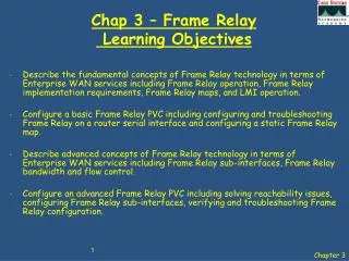
Packet Switched - Frame Relay • Frame Relay VCs are uniquely identified by a DLCI, which ensures bidirectional communication from one DTE device to another. • Most Frame Relay connections are PVCs rather than SVCs.
Frame Relay Operates at OSI Layers 1 and 2. Initially designed to work with ISDN. A streamlined version of X.25. Uses 2 types of connection: Switched Virtual Circuits (SVCs). Permanent Virtual Circuits (PVCs).
Frame Relay Frame Relay is a packet-multiplexed interface in a packet switching environment (Developed by Cisco). In the US, frame relay uses T1 (up to 1.5Mbps) and T3 (up to 45Mbps) connections. In Europe, frame relay supports E1 (up to 2.044Mbps) and E3 (up to 34.36Mbps.) The DTE (router) and the DCE (switch) can multiplex various connections over a common medium by way of virtual circuits. Designed for reliable digital / fibre environments, so it has little need of the error checking overheads that come with X.25.
Packet Switching - Issues The variety of packet and frame sizes make traffic handling unpredictable in a packet switched network P4 P4 P3 P3 P2 P2 P1 P1 Packet Switch • The size of packet P1 is serviced first, delaying packets P2-P4
All data frames are broken up into fixed length cells, which allows them to be transmitted with predictability and uniformity Cell Switched - Asynchronous Transport Mode(ATM) P4 P3 P2 P1b P1c P1a P4 P1c P3 P1b P2 P1a Cell Mux • A cell is defined as a small, fixed-sized block of information
Cell Switched - Asynchronous Transport Mode(ATM) • A shared network technology that offers very low latency and jitter at much higher bandwidths than frame relay. • Capable of transferring voice, video, and data through private and public networks. • Built on a cell-based architecture rather than on a frame-based architecture.
Internet Connection – Digital Subscriber Link (DSL) • DSL technology is an always-on connection technology that uses existing twisted-pair telephone lines to transport high-bandwidth data, and provides IP services to subscribers
What is DSL? • DSL uses the high frequency range of up to about 1 MHz. • For example, asymmetric digital subscriber line (ADSL) uses the frequency range of about 42 kHz to 1MHz. • ADSL does not overlap the Plain Old Telephone Service (POTS) voice frequency range. (300 – 4000 Hz) • POTS and ADSL service can coexist over the same wire.
ADSL channels and encoding • DMT (Discrete Multitone Modulation) • DMT divides signals into separate channels. • DMT divides the data into 250 separate channels, each 4 kHz wide. • Each channel is monitored. • If the quality is too impaired, the signal is shifted to another channel. This system constantly shifts signals between different channels, searching for the best channels for transmission and reception.
Internet Connection – Cable Modem • Coaxial cable is widely used in urban areas to distribute television signals. • Network access is available from some cable television networks - allows for greater bandwidth than the conventional telephone local loop.
Cable Modem • Cable modems provide an always-on connection and a simple installation. • A cable modem is capable of delivering up to 30 to 40 Mbps of data on one 6 MHz cable channel. • With a cable modem, a subscriber can continue to receive cable television service while simultaneously receiving data to a personal computer.
Internet Connection – Broadband Wireless • Municipal WiFi • WiMax (IEEE 802.16) • Satellite
Virtual Private Networks(VPN) • To address security concerns when network resources are accessed remotely over the Internet, broadband services provide capabilities for using Virtual Private Network (VPN) connections to a VPN server. • A VPN is an encrypted connection between private networks over a public network such as the Internet. Instead of using a dedicated Layer 2 connection such as a leased line, a VPN uses virtual connections called VPN tunnels, which are routed through the Internet to connect LAN resources.
Chap 1 – Services in a Converged Network Learning Objectives • Describe how the Cisco Enterprise Composite Model (ECNM) provides integrated services over an Enterprise network. • Describe the key WAN technology concepts. • Identify the appropriate WAN technologies to use when matching ECNM best practices with typical enterprise requirements for WAN communications.
Any Questions?