Download
1 / 30
300 likes | 482 Views
The SXR Instrument. The SXR is a instrument for Soft X-ray Materials Research on the LCLS SXR is the second soft x-ray instrument at the LCLS SXR is compatible with multiple techniques for studying materials with ultra short soft x-rays pulses

E N D
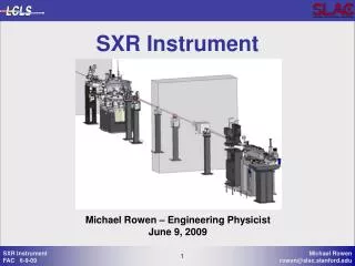
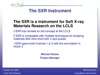
The SXR Instrument The SXR is a instrument for Soft X-ray Materials Research on the LCLS SXR is the second soft x-ray instrument at the LCLS SXR is compatible with multiple techniques for studying materials with ultra short soft x-rays pulses SXR spans both hutches 1 & 2 with the end station in Hutch 2 SXR compliments the AMO experiment Michael Rowen Project Engineer
Scientific Drivers for SXR • X-Ray Scattering Spectroscopy on Strongly Correlated Materials • Pump-Probe Ultrafast Chemistry • Magnetic Imaging • Ultrafast Coherent Imaging
Science Driven Requirements • Soft X-ray Beam Line, 500*-2000eV: • Monochromatic, E/DE of ~5000 • Focused or unfocused beam at end station • Switch between monochromatic and “white” beam without moving experimental system • Open end station for interchangeable user systems • Capabilities for fast, single shot, transmission spectroscopy • * LCLS operations will be at photon energies >825eV in the near term.
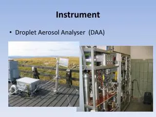
SXR Beam Line • Major Components: • Monochromator • Exit slit • Focusing Optics • No fixed end station • Transmission sample chamber (up stream of mono) • Spectrometer detector (insertable, at exit slit)
SXR Layout Basic AMO & SXR layout in hutches 1 & 2
Grating Monochromator • Varied Line Spacing (VLS) grating monochromator: • 2 optical elements (vertically deflecting): spherical mirror, VLS plane grating • Energy scan by rotation of grating • Erect focal plane for spectrometer mode and fixed slit position. • B4C coated optics Courtesy Phil Heimann
Monochromator Layout M1 Mirror & Grating Exit Slit Monochromator spans the first and second hutches
Resolution vs Energy 200 l/mm grating • 100 l/mm grating At 800 eV DE = 0.19eV At 1200 eV DE =0.23 eV Resolution goal of 0.2 eV at 1000 eV is achieved.
Optical tolerances • The figure tolerances are difficult because we need to preserve the brightness of a source 100 mm in diameter and at a 100 m distance. • That accuracy has been achieved by two venders for the LCLS SOMS and HOMS mirrors.
Grating efficiency • Grating efficiency calculations with Gsolver by Phil Heimann.
Fourier optics simulations • From Jacek Krzywinski • At the exit slit. • Assuming 2 nm rms figure error.
Fourier optics simulations (cont.) X profile Y profile • At the focus in end station. • Assuming 2 nm rms figure error.
Behind the focus (10 cm) • When the focus of the KB mirrors are not at the sample, there is more structure in the beam. • The peak intensity is still reduced, here by ~1/100.
Pulse duration preservation • Pulse stretching: N m l = 40 fs at 826 eV (i.e. at high dispersion) • An adjustable aperture near grating can be used to reduce pulse stretching with a decreased intensity and energy resolution. • For dispersive measurements and white beam, LCLS pulse duration is unaffected.
Focusing Optics • K-B Optics: • Silicon Substrates • Profiled mirrors bent to elliptical cylinders • Focus to <10x10mm • B4C coatings • Un-bend one or both mirrors for line or unfocused beam
K-B Refocusing Mirrors • K-B Mirrors Focus End Station <10x10 mm
Use ALS beamline mechanical designs • ALS “standard” monochromator: 0.1 mrad motion of pre-mirror and grating, Horizontal translation of chamber. • ALS bendable mirror: Motorized leaf springs, Flange mounted. • Plan to use existing mechanical designs with minimal modifications in the LCLS SXR Instrument.
Optical Design Review 7/15/08 • Committee • Peter Stefan (SLAC) chair, Alistair MacDowell (ALS), Rolf Follath (BESSY) • General comments • “Overall, the review committee felt that the optical design presented is good, and will likely work. The assembled SXR design team has good experience in this area and a good ‘track record.’ Also, the damage issues seemed properly considered.” • Specific recommendations • Because of the as-coated density of B4C, the mirror incidence angles were changed 15 -> 14 mrad. • The Fourier optics calculations were repeated with the correct orientation between the offset mirrors and the monochromator.
Spectrometer Mode • Transmission Sample Location Spectrometer Detector at Exit Slit
PM1 F1 Spectrometer Csp PM2 Oscope Laser Oscillator Controls /2-1 Laser Hall PMOsc F2 Hutch 2 PM4 PM3 C2 M2 VEC C5 M1 /2-2 L2 L1 /2-3 Harmonics C1 To Experiment L4 M4 C4 M3 To Experiment L3 L5 2VEC AC C3 /2-4 PM5 Pump Laser System Replicate system from AMO Courtesy Greg Hays
SXR / AMO Interfaces AMO & SXR engineers are working closely to resolve all conflicts as the are identified. • Space is tracked • Systems checked for compatibility • Ideas and designs are shared (i.e. mostly stolen from AMO and LUSI) • Operational boundaries have been defined
Space between instruments is closely tracked Minimize diameter SXR beam pipe Clears AMO instrumentation
AMO K-B optics and SXR Mono being designed by the same engineer Space for extension AMO into 2nd Hutch Rack space is apportioned
Operations • Operations on the SXR beam line requires installation of the monochromator which is scheduled for installation winter shutdown ’09-‘10. • Initial operational mode: No access to hutches with beam, i.e. no access to Hutch 1 when AMO is running.(July –Dec ‘09) • Intermediate operational mode: No access to hutches with active experiments. Access to hutches with beam passing through. (as soon after start of SXR operations as possible, ~Mar ‘10) • Final operational mode: Access to hutches with active soft x-ray experiments, Hutch 1 or Hutch 2. • SXR is working with Radiation Physics on defining and building in the necessary shielding and controls for access soon after SXR operations start. • Operations with samples in the transmission chamber (Hutch 1) for spectrograph mode will require additional approvals, testing and implementation of a shielding plan.
Endstations 8 Endstations described in the TDR document Stöhr Chapman Nilsson Hussein-Shen
Institutional Roles Total estimated cost:
SXR Status • The SXR scientific case has been reviewed by SAC. • Technical Design Report (TDR) has been written and accepted. • LCLS has reviewed the project for compatibility. • The X-ray optical design has been reviewed. • The base MoU is signed. • Integration of SXR into the LCLS construction project has started. • Proposals for Long lead optical components are coming in and the first contracts have been placed.
Status of MoU • The MoU between SLAC and DESY has been signed by DESY and SLAC. • The technical addendum defining contributions and roles of the members of the consortium is in final draft and should be completed by ??.
SXR Schedule SXR is just starting to be integrated into the LCLS schedule. These completion dates are the earliest possible dates. Expected final installations are in Dec ’09/Jan ’10.
SXR Instrument team • Anders Nilsson (Stanford) & Wilfried Wurth (Hamburg): consortium leaders • Phil Heimann & Nicholas Kelez (ALS): monochromator and KB optics • Yves Acremann (Stanford) & Alexander Foehlisch (Hamburg): diagnostics and with Bill White & Greg Hays (LCLS) laser beam delivery • Stefan Moeller (LCLS): LCLS contact • Gunther Haller, Perry Anthony, Dave Nelson (SLAC): controls • Amedeo Perazzo, Chris O’Grady & Remi Machet: data acquisition • Jacek Krzywinski (LCLS): fourier optics simulations • Regina Soufli (LLNL): optical coatings • Michael Rowen* (LCLS/SLAC) : overall beam line systems, budget, schedule, interfaces • *Only full-time person.