Download
1 / 53
530 likes | 659 Views
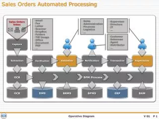
Capture Bar. Business Owner , BO. Architect , AR. Consulting Engineer, CE. Contractor, CR. General. Restaurant employees are continuously exposed to environmental tobacco smoke in their work places. General.

E N D
Capture Bar Business Owner , BO Architect , AR Consulting Engineer, CE Contractor, CR Capture Bar
General Restaurant employees are continuously exposed to environmental tobacco smoke in their work places. Capture Bar
General The amount of environmental tobacco smoke cannot be sufficiently reduced through standard ventilation. Capture Bar
General However, ventilation techniques can significantly reduce employee exposure to environmental tobacco smoke emitted within static workplaces like bars. Capture Bar
General Legislation limits smoking in most of European countries. Capture Bar
Capture Bar • Local ventilation solution for bars and restaurants • Developed to protect restaurant employee from environmental tobacco smoke Capture Bar
Operation Principle of Capture Bar Capture Bar
The Purpose of Air Curtain Capture Bar
The Purpose of Supply Air Capture Bar
The Purpose of Exhaust Capture Bar
CONTROL DIAGRAM Stand-alone Control Temperature control of air curtain The temperature set point for air curtain is 28 ºC. The temperature is controlled based on duct sensor (TE1) and electrical heating coil (EA1). The power of electrical heater is proportionally increased, if the duct temperature decreases below the set point. Correspondingly, the heater power is decreased when duct temperature increases. Pressure difference switch (PDS1) shall cut off the heater power (EA1) when the duct pressure, and therefore the air flow, is below the minimum limit, set point 10 Pa. The duct heater shall be equipped with two overheating cut-outs. Set point for automatic reset is 60 ºC and set point for manual reset is 120 ºC. Temperature control of supply air The temperature set point for supply air into working area is defined by a manual set point adjustment (HS2), range 18 – 24 ºC. The temperature is controlled based on duct sensor (TE2) and electrical heating coil(s) (EA2.1, EA2.2). The power of electrical heater is proportionally increased, if the duct temperature decreases below the set point. Correspondingly, the heater power is decreased when duct temperature increases. The pressure difference switch (PDS2.1) shall cut off the heater power (EA2.1) and pressure difference switch (PDS2.2) shall cut off the heater power (EA2.2) when the corresponding duct pressure, and therefore the air flow, is below the minimum limit, set point 10 Pa. The duct heaters shall be equipped with two overheating cut-outs. Set point for automatic reset is 60 ºC and set point for manual reset is 120 ºC. Working area supply air flow shall be shut off by damper FZ2, if needed. Bill of materials EA1 Duct heater TE1 Duct temperature sensor TC1 Temperature controller PDS1 Pressure difference switch EA2.1 Duct heater EA2.2. Duct heater TC/HS2 Temperature controller and manual set point adjustment TE2 Duct temperature sensor PDS2.1. Pressure difference switch PDS2.2 Pressure difference switch FZ2 Shut-off damper Capture Bar
Capture Bar Restaurants • Hotel Seurahuone, Sevilla restaurant, Turku, Finland • Hotel Lappee, Doris night club, Lappeenranta, Finland • Hotel Ilves, Tampere, Finland • Sports Academy, Iso Omena, Espoo, Finland • Ale Pub, Helsinki, Finland • Friday, Helsinki, Finland • Kumpeli, Heinola, Finland • Hotel Vaakuna, Kouvola, Finland • Hotel Vaakuna, Rovaniemi, Finland Capture Bar
Hotel Lappee, Finland,Doris Nightclub Capture Bar
Hotel Kumpeli, Finland Capture Bar
Maintenance Pull the tray out from the balancing box. Wash/dry the tray and push it back to the balancing box until it clips into position. Capture Bar
Measurement results Capture Bar
Capture Bar CFD -animation Capture Bar
Benefits Capture Bar
SBB-Air Curtain Unit in Bar Desk Capture Bar
Materials • SBB air curtain: stainless steel AISI304 • Supply air units: painted steel, RAL colours • Exhaust air units: painted steel, RAL colours Capture Bar
Model Length of the balancing box (mm) Required hole to the desk (length*width, mm) Length of the slot (mm) SBB-400 390 375 x 30 404 SBB-700 690 675 x 30 704 SBB-756 756 741 x 30 770 SBB-1000 990 975 x 30 1004 SBB-Dimensions SBB-air curtain unit dimensions (SBB- 400 / 700 / 756 / 1000): SBB-air curtain slot dimensions (SBB- 400 / 700 / 756 / 1000): Capture Bar
Pressure Drop and Sound Data Capture Bar
Design Instructions Air curtain SBB • Air flow 20…25 l/s, run meter • Slot opening 7 mm • Air jet about 70o from horizontal level in direction of customers • Cleanable • Material RST/HFe Capture Bar
Design Instructions Testing of air curtain with tracer gas Too lowjet velocity v = 0,7 m/s Recommendedjet velocityv = 3,0 m/s Capture Bar
Design Instructions Standard low velocity units (e.g. AFF) to the ceiling above employee: • design air flow about 50-100 l/s,m2 Placing of supply air either: • back wall • furniture base • pillar • ceiling Capture Bar
Design Instructions Standard exhaust units (EVA, URH etc.): • installed mainly in smoking permitted area • air flow rate is depending on total air balance • recommendation: 75% of total exhaust air volume from within the smoking area Capture Bar
Ductwork Capture Bar
CONTROL DIAGRAMDDC Control System Temperature control of air curtainThe temperature set point for air curtain is always +2 ºC higher than actual room air temperature (TE1). The air curtain temperature is controlled based on duct sensor (TE2) and electrical heating coil (EA2). The power of electrical heater is proportionally increased, if the duct temperature decreases below the set point. Correspondingly, the heater power is decreased when duct temperature increases. The temperature controller shall cut off the heater power when the air handling unit is switched off. Pressure difference switch (PDS2) shall cut off the heater power when the duct pressure, and therefore the air flow, is below the minimum limit, set point 10 Pa.The duct heater shall be equipped with two overheating cut-outs. Set point for automatic reset is 60 ºC and set point for manual reset is 120 ºC.Recommended air flow rate is 25 dm3/s, run meter. Temperature control of supply airThe temperature set point for supply air into working area is defined by a manual set point adjustment (HS3), range 18 – 22 ºC. The temperature is controlled based on duct sensor (TE3) and electrical heating coil (EA3). The power of electrical heater is proportionally increased, if the duct temperature decreases below the set point. Correspondingly, the heater power is decreased when duct temperature increases. The temperature controller shall cut off the heater power when the air handling unit is switched off. The pressure difference switch (PDS3) shall cut off the heater power (EA3) when the duct pressure, and therefore the air flow, is below the minimum limit, set point 10 Pa. The duct heater shall be equipped with two overheating cut-outs. Set point for automatic reset is 60 ºC and set point for manual reset is 120 ºC.Recommended air flow rate into working area is 50 –100 dm3/sm2. CONTROL PANEL AUXILARY DEVICES MOTOR CONTROL CENTER DI, AlarmDI, Indication DD AIAD SUPPLY FAN SUPPLY AIR TEMPERATURE+ 18...+22oC CURTAIN AIR+2oC OVER ROOM TEMPERATURE Capture Bar
Developing the Solution • Computerized flow simulation (CFD) was utilized in the development of the system • Tracer gas measurements were used in optimisation of the system • Regional Institute of Occupational Health has tested the system in hotel Lappee’s nightclub Capture Bar
Developing the Solution Tracer gas measurements in laboratory Smoke tests in laboratory Capture Bar
Field Surveys Hotel Lappee, Doris Night Club Capture Bar
Hotel Lappee, Doris Night Club • Restaurant is divided to smoking and non-smoking areas without separation walls or other arrangements preventing smoke flow • Another bar desk is situated within a smoking area and another in non-smoking area • Customers 430 • Area 529 m2 • Volume 1517 m3 Capture Bar
Measurement pointsin Night Club N = Nicotine measurement M= Tracer gas measurements H = Particle measurement 1. Bar working area 2. Bar working area 3. Exhaust air 4. Bar desk customer area 5. Bar working area 6. Customer area ceiling HNM N MNH MH M H M M H 1. 4. 5. 2. 3. 6. = smoking prohibited area Hotel Lappee Doris Capture Bar
Field Surveys Particle measurement (H)Laser particle indicator in the ceiling of customer area Tracer gas emission (M)Emission outlets in the bottom of the bar desk Nicotine measurement Dose indicatorin the breathing zone ofemployee Capture Bar
Measurement Methods • Tracer gas methods • Step down method • Step up method • Particle analysis • Temperature measurements • Nicotine measurements • Air flow rate and velocity measurements Capture Bar
Tracer Gas Measurements 1. Bar working area2. Bar working area3. Exhaust air4. Bar desk customer area5. Bar working area6. Customer area ceiling Tracer gas SF6 concentration (ppm) Time Capture Bar
Field Survey Results • Hotel Lappee, Doris night club • It was possible to reduce working area nicotine concentration • to 1/10 from average restaurant concentrations • Up to 95% protection efficiency Capture Bar
SBB Air Curtain Part List 1. 5. One unit consist of: 1.Balancing box (1 pcs) 2.Slot (1 pcs) 3.Tray (1 pcs) 4.Fixing bracket (2-3 pcs) 5.Fixing bolt M5 (2-3 pcs) 6.Fixing list (a/b) depending on the assembly 4. 2. 6. 3. Capture Bar
SBB Air Curtain Installation tothe Bar Desk 1.Dismantle the tray from the balancing box. Capture Bar
SBB Air Curtain Installation tothe Bar Desk 2. Place the balancing box under the desk plate. Capture Bar
SBB Air Curtain Installation tothe Bar Desk 3. Fix the front of the box to the desk with screws. Capture Bar
SBB Air Curtain Installation tothe Bar Desk 4.Check the horizontal straightness of the box. Capture Bar
SBB Air Curtain Installation tothe Bar Desk 5.Fix the back of the box to the desk plate or to the front panel of the desk with screws. Capture Bar
Slot Installation 6. Set the slot to the desk opening so that Halton-logo is readable from customer side. Capture Bar
Slot Tightening 7.Tighten the screws equally. Capture Bar
Slot Tightening 8. Tighten the slot equally to the desk with fixing brackets. Capture Bar
Installation of the Tray 9. Put the tray back to the balancing box. Capture Bar
Connecting the Supply Air Ductwork to the Balancing Box 10.Connect the supply air ductwork to the balancing box and adjust the airflow. Capture Bar
Commissioning and Maintenance • Adjusting air flows before commissioning • Cleaning of air curtain unit trays Capture Bar
Benefits of Capture Bar • Employees and customers exposure to tobacco smoke reduces • Cleaner indoor air improves satisfaction, health and job productivity Capture Bar