Download
1 / 91
950 likes | 1.19k Views
A Study of Stacked Arrays of Yagi-Uda Antennas. Jay Terleski, WX0B. 1. 15m Example 120/90/65. WX0Bs 10 and. 15 m stacks. 2. 15m Example.

E N D
A Study of Stacked ArraysofYagi-Uda Antennas Jay Terleski, WX0B 1
15m Example 120/90/65 WX0Bs 10 and 15 m stacks 2
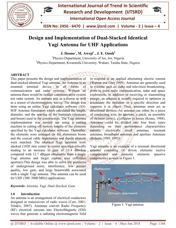
15m Example A good model which applies to 20 and 10 meters will be a 4 element 23 foot design. Most antenna manufactures offer a similar antenna to this design. 40 meters we will will use 2 and 3 element beams common to Hams. 3
Why do we stack yagis • Gain • Clean up pattern • Control of Take-off angle • Beam in multiple directions • Suppress rain, snow, wind static 4
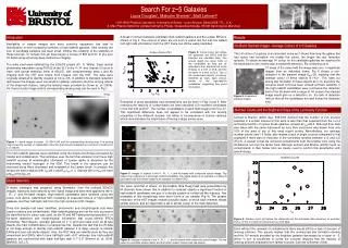
Gain Single 15m yagi at 125 feet 14.71 dbi gain @ 5 5
Gain 125/95 stack with 17.01 dbi gain @ 6 degrees 6
Gain 120/90 stack with 17.01 dbi gain @ 6 degrees 125/95/65 stack 18.34 dbi gain @ 6 degrees 7
Gain 125/95/65/35 stack 18.54 dbi gain @ 7 degrees 8
Why do we stack yagis • Gain • Control of Take-off angle 9
Control of Take-off angle 35ft lower one in stack 14 dbi @23 degrees 10
Control of Take-off angle 65/35 lower two in stack 16.3dbi gain @ 12 deg 11
Control of Take-off angle 95/65 middle two in stack 16.64 dbi @ 8 degrees 12
Control of Take-off angle 125/95/65 top 3 in stack 18.43 @ 6 degrees 13
Control of Take-off Angle 95/65/35 lower 3 in stack 17.54 dbi @ 9 degrees 14
Control of Take-off Angle 125/35 upper lower in stack 15.91dbi @ 27 degrees 15
Control of Take-off Angle 95/35 lobes at 9, 32, 54 degrees are possible 16
Why do we stack yagis • Gain • Clean up pattern • Control of Take-off angle Both out of phase - BOP mode 17
BOP 43 m 32 m 18
BIP both in Phase 42m/32m 125/95 17.3 dbi @ 6 degrees BIP 19
BOP 180 degrees out 42/32 m 125/95 BOP 180 degrees 15 dbi 39 deg 20
BIP / BOP Comparison both in Phase and Both out of Phase 20a
0 delay 0 delay 180 delay 180 delay 4 high BOP or FOP 21
Four in phase FIP FIP 18.54 dbi gain @ 7 degrees 22
FOP FOP 17.67 dBi @ 17 degrees, bottom 2 BOP 23
FIP / FOP FIP 18.54 dbi gain @ 7 degrees FOP 17.67 dBi @ 17 degrees 23
Some BOP rules Gain is always less at main lobe Phase delays that are not 180 do not work ! OR DO THEY??? 25
0 delay 0 delay -90 delay -90 delay Can other angles be used to change angles? 23
FOP lower 2 -90 degrees Smeared and loss of gain 15.52 dBi @ 7 degrees Loss of exactly 3db at 7 degrees 24
Can other angles be used to change angles? FIP 18.54 dbi gain @ 7 degrees 15.52 dBi @ 7 degrees -3db at lower lobe lost but at 25 degrees the gain is +20db more ! 23
Some BOP rules Gain is always less at main lobe But the gain may be better at all the nulls. Lets test this on two beams 25
Fill in pattern by adding delay 17 dBi 15 dBi 15m 2 stack at 0 degrees 15m 2 stack at -90 degrees phase relationship delay of bottom beam 26
Apparatus 25
Narrow beam Target area 25
What are the effects of Boom length and spacing Example: Short booms vs. spacing C3 stack or any short Yagi. 27
Boom length and spacing C3 @ 95 feet 12.01 dBi @ 7 degrees 28
Boom length and spacing 30 ft space 14.97 dBi gain @ 8 degrees - bad lobe goin UP! 29
Boom length and spacing 25 ft space Great pattern - gain 15.28 dBi @ 8 degrees 30
Boom length and spacing 27 ft space Short booms vs. spacing C3 stack or any short Yagi. Just right 15.46 dBi @ 8 degrees 31
Boom length and spacing How to calculate the best spacing based on boom length? 32
Boom length and spacing S (WL) = ( Boom Length in WL) • 1.0 WL booms = 1 WL spacing • .75 WL booms = .87 WL spacing • .5 WL booms = .707 WL spacing • .25 WL booms = .5 WL spacing • Short booms are very critical, model it to be certain. 33
What about stacking Dissimilar antennas? Matching technique - are they the same? Driven element offsets must be know. Baluns are they the same? 34
3 foot offset Dissimilar antenna stacks • It can be done with certain precautions • Example 3 ele with 4 ele 15 m. • Same match, same balun 34
Dissimilar antenna stacks Slurred pattern less gain 15.7 dbi @ 6 degrees 35
Dissimilar antenna stacks 3 feet / 44.4 ft (WL) X 360 degrees = 24.3 degrees of delay is required to put these antennas in phase. 3 feet X .66 (VF of RG213) = 1.98 feet of coax would need to be added to the leading driven element. Lets correct the model by adding in the delay line and see the resulting pattern 36
Dissimilar antenna stacks Well defined nulls, more gain, 17.03 dBi @ 6 degrees a gain of 1.33 dBi 37
Dissimilar antenna stacks Well defined nulls, more gain, 17.03 dBi @ 6 degrees a gain of 1.33 dBi Slurred pattern less gain 15.7 dbi @ 6 degrees 37
3 foot offset Dissimilar antenna stacks What if Beams, Matching and Baluns are not the same? Gamma matched balun X Hairpin matched & balun Y 37
Dissimilar antenna stacks O-Scope, equal feed lines, and a friend are needed. 37
Dissimilar antenna stacks Measure the angle of delay needed to align pattern Build a coax delay line and add to the leading antenna’s feed line. 37