Download
1 / 46
470 likes | 672 Views
MAGNETICALLY COUPLED NETWORKS. LEARNING GOALS. Mutual Inductance Behavior of inductors sharing a common magnetic field. Energy Analysis Used to establish relationship between mutual reluctance and self-inductance. The ideal transformer

E N D
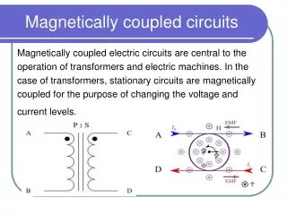
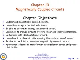
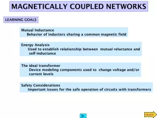
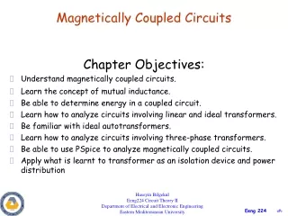
MAGNETICALLY COUPLED NETWORKS LEARNING GOALS Mutual Inductance Behavior of inductors sharing a common magnetic field Energy Analysis Used to establish relationship between mutual reluctance and self-inductance The ideal transformer Device modeling components used to change voltage and/or current levels Safety Considerations Important issues for the safe operation of circuits with transformers
BASIC CONCEPTS – A REVIEW Ampere’s Law (linear model) Faraday’s Induction Law Assumes constant L and linear models! Ideal Inductor Total magnetic flux linked by N-turn coil Magnetic field
Induced links on second coil If linkage is created by a current flowing through the coils… (Ampere’s Law) The voltage created at the terminals of the components is (Faraday’s Induction Law) What happens if the flux created by the current links to another coil? One has the effect of mutual inductance MUTUAL INDUCTANCE Overview of Induction Laws Magnetic flux
Self-induced Mutual-induced Linear model simplifying notation TWO-COIL SYSTEM (both currents contribute to flux)
THE ‘DOT’ CONVENTION Dots mark reference polarity for voltages induced by each flux COUPLED COILS WITH DIFFERENT WINDING CONFIGURATION
Special case n=2 A GENERALIZATION Assume n circuits interacting
LEARNING EXAMPLE Currents and voltages follow passive sign convention Flux 2 induced voltage has + at dot THE DOT CONVENTION REVIEW For other cases change polarities or current directions to convert to this basic case
Voltage terms LEARNING EXAMPLE Mesh 1
Voltage Terms LEARNING EXAMPLE - CONTINUED Mesh 2
More on the dot convention Equivalent to a negative mutual inductance
PHASORS AND MUTUAL INDUCTANCE Phasor model for mutually coupled linear inductors LEARNING EXTENSION Convert to basic case Assuming complex exponential sources
The coupled inductors can be connected in four different ways. Find the model for each case CASE I Currents into dots Currents into dots CASE 2 LEARNING EXAMPLE
Currents into dots Currents into dots CASE 4 CASE 3
LEARNING EXAMPLE 1. Coupled inductors. Define their voltages and currents 2. Write loop equations in terms of coupled inductor voltages 3. Write equations for coupled inductors 4. Replace into loop equations and do the algebra
LEARNING EXAMPLE Write the mesh equations 3. Write equations for coupled inductors 4. Replace into loop equations and rearrange terms 1. Define variables for coupled inductors 2. Write loop equations in terms of coupled inductor voltages
LEARNING EXTENSION 1. Define variables for coupled inductors Voltages in Volts Impedances in Ohms Currents in ____ 2. Loop equations 3. Coupled inductors equations 4. Replace and rearrange
LEARNING EXTENSION WRITE THE KVL EQUATIONS 1. Define variables for coupled inductors 2. Loop equations in terms of inductor voltages 3. Equations for coupled inductors 4. Replace into loop equations and rearrange
WARNING: This is NOT a phasor LEARNING EXAMPLE DETERMINE IMPEDANCE SEEN BY THE SOURCE 1. Variables for coupled inductors 2. Loop equations in terms of coupled inductors voltages 3. Equations for coupled inductors 4. Replace and do the algebra
LEARNING EXTENSION DETERMINE IMPEDANCE SEEN BY THE SOURCE 1. Variables for coupled inductors 2. Loop equations 3. Equations for coupled inductors 4. Replace and do the algebra One can choose directions for currents. If I2 is reversed one gets the same equations than in previous example. Solution for I1 must be the same and expression for impedance must be the same
Coefficient of coupling ENERGY ANALYSIS We determine the total energy stored in a coupled network This development is different from the one in the book. But the final results is obviously the same
Merge the writing of the loop and coupled inductor equations in one step Circuit in frequency domain Compute the energy stored in the mutually coupled inductors LEARNING EXAMPLE Assume steady state operation We can use frequency domain techniques
LEARNING EXTENSION Go back to time domain
Insures that ‘no magnetic flux goes astray’ Ideal transformer is lossless Circuit Representations THE IDEAL TRANSFORMER First ideal transformer equation Since the equations are algebraic, they are unchanged for Phasors. Just be careful with signs Second ideal transformer equations
For future reference Phasor equations for ideal transformer REFLECTING IMPEDANCES
Strategy: reflect impedance into the primary side and make transformer “transparent to user.” Determine all indicated voltages and currents LEARNING EXAMPLE SAME COMPLEXITY CAREFUL WITH POLARITIES AND CURRENT DIRECTIONS!
Strategy: reflect impedance into the primary side and make transformer “transparent to user.” LEARNING EXTENSION LEARNING EXTENSION Voltage in Volts Impedance in Ohms ...Current in Amps Strategy: Find current in secondary and then use Ohm’s Law
Replace this circuit with its Thevenin equivalent Equivalent circuit with transformer “made transparent.” USING THEVENIN’S THEOREM TO SIMPLIFY CIRCUITS WITH IDEAL TRANSFORMERS Reflect impedance into secondary One can also determine the Thevenin equivalent at 1 - 1’ To determine the Thevenin impedance...
Find the Thevenin equivalent of this part Equivalent circuit reflecting into primary Equivalent circuit reflecting into secondary USING THEVENIN’S THEOREM: REFLECTING INTO THE PRIMARY Thevenin impedance will be the the secondary mpedance reflected into the primary circuit
Equivalent circuit reflecting into secondary Equivalent circuit reflecting into primary LEARNING EXAMPLE Draw the two equivalent circuits
Thevenin equivalent of this part LEARNING EXAMPLE But before doing that it is better to simplify the primary using Thevenin’s Theorem This equivalent circuit is now transferred to the secondary
Transfer to secondary Circuit with primary transferred to secondary LEARNING EXAMPLE (continued…) Thevenin equivalent of primary side
Notice the position of the dot marks Equivalent circuit reflecting into primary LEARNING EXTENSION
Transfer to secondary LEARNING EXTENSION
Phasor equations for ideal transformer LEARNING EXAMPLE Nothing can be transferred. Use transformer equations and circuit analysis tools 4 equations in 4 unknowns!
Good neighbor runs an extension and powers house B SAFETY CONSIDERATIONS: AN EXAMPLE Houses fed from different distribution transformers Braker X-Y opens, house B is powered down When technician resets the braker he finds 7200V between points X-Z when he did not expect to find any
LEARNING BY APPLICATION Why high voltage transmission lines? CASE STUDY: Transmit 24MW over 100miles with 95% efficiency A. AT 240V B. AT 240kV
LEARNING EXAMPLE Rating a distribution transformer Determining ratio Determining power rating
LEARNING EXAMPLE Battery charger using mutual inductance Smaller inductor Assume currents in phase
“NOISE” CASE 1: AC MOTOR (f=60Hz) CASE 2: FM RADIO TRANSMITTER !!! APPLICATION EXAMPLE INDUCED ELECTRIC NOISE
NO LOAD! LEARNING EXAMPLE LINEAR VARIABLE DIFFERENTIAL TRANSFORMER (LVDT)
Complete Analysis Assuming zero- phase input Design equations for inductances FOR EXAMPLE LVDT - CONTINUED
Auto transformer connections Circuit representations LEARNING BY DESIGN Use a 120V - 12V transformer to build a 108V autotransformer Conventional transformer Use the subtractive connection on the 120V - 12V transformer
Design constrains and requirements Transformer turn ratio Notice safety margin Specify 100mA rating for extra margin! Transformers DESIGN EXAMPLE DESIGN OF AN “ADAPTOR” OR “WALL TRANSFORMER”