Download
1 / 28
330 likes | 722 Views
Estimation of IQ vector components of RF field - Theory and implementation. M. Grecki , T. Jeżyński, A. Brandt. Agenda. Introduction - LLRF system Downconversion and IQ estimation VHDL implementation of IQ estimator Sources of incorrectness

E N D
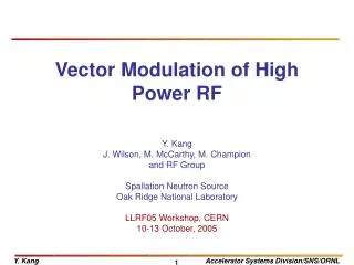
Estimation of IQ vector components of RF field - Theory and implementation M. Grecki, T. Jeżyński, A. Brandt
Agenda • Introduction - LLRF system • Downconversion and IQ estimation • VHDL implementation of IQ estimator • Sources of incorrectness • Simulation and optimization of IQ estimation parameters (IF, SF) • Conclusion
Agenda • Introduction - LLRF system • Downconversion and IQ estimation • VHDL implementation of IQ estimator • Sources of incorrectness • Simulation and optimization of IQ estimation parameters (IF, SF) • Conclusion
LLRF control system wector modulator LO - Local Oscillator rf switch Klystron RF power waveguide ~ ~ ~ ~ wave guide tuner wave guide tuner ~ ~ Ainc Ainc timing Aref Aref HV beam FT PZT FT PZT .... I Q cav.n cav.1 DAC ADC ADC ADC ADC DAC DAC DAC ADC ADC ADC ADC FPGA Digital feedback VME FPGA computational algorithm [aij] cav A DOOCS server Control panel + + [bij] cav B ... Feed forward table Gain table Setpoint table [zij] cav Z
Agenda • Introduction - LLRF system • Downconversion and IQ estimation • VHDL implementation of IQ estimator • Sources of incorrectness • Simulation and optimization of IQ estimation parameters (IF, SF) • Conclusion
Problem: xrf xif xif=xrf·xlo • signal downconversion • I and Q estimation xlo F() rf- lo lo rf rf+ lo
System migration Now: IF = 250kHz SF = 1MHz TS = 1us 4 samples / IF signal period prediction needed Future: IF = 81MHz ? SF = 36MHz ? TS = 1us many samples per TS averaging possible (noise reduction)
AD Conversion parameters • Constant SF (time uniform sampling) • M·IF=N·SF (M,N –integer numbers) • TS=1s, IF >= 1MHz • SF >= 3MHz, limited by ADC parameters • SF - averaging => noise reduction • SF - ADC accuracy drops down • IF - ADC accuracy drops down
Agenda • Introduction - LLRF system • Downconversion and IQ estimation • VHDL implementation of IQ estimator • Sources of incorrectness • Simulation and optimization of IQ estimation parameters (IF, SF) • Conclusion
IQ estimation IF=81MHz, SF=36MHz reset entity IQestim is port (I : buffer BREG; -- I output Q : buffer BREG; -- Q output iqr : out bit; -- IQ output ready S : in BREG; -- sample input sr : in bit; -- sample ready input clk : in bit; reset : in bit); end; clk S sr I Q iqr
Numerical algorithm sin 14b int cos -213 < xi < 213-1 14b int xi 18x18 -213 < sin, cos < 213-1 28b int >>8 >>8 24b int 32b int The computation algorithm assures ~14bits accuracy of results >>5 >>5 *int(218/M) *int(218/M) >>17 >>17 I Q 14b int
VHDL implementation Design Summary -------------- Target Device : x2v4000 Target Package : ff1152 Target Speed : -6 Logic Utilization: Total Number Slice Registers: 64 out of 46,080 1% Number used as Flip Flops: 62 Number used as Latches: 2 Number of 4 input LUTs: 55 out of 46,080 1% Logic Distribution: Number of occupied Slices: 43 out of 23,040 1% Number of Slices containing only related logic: 43 out of 43 100% Number of Slices containing unrelated logic: 0 out of 43 0% *See NOTES below for an explanation of the effects of unrelated logic Total Number 4 input LUTs: 80 out of 46,080 1% Number used as logic: 55 Number used as a route-thru: 25 Number of bonded IOBs: 46 out of 824 5% IOB Flip Flops: 29 Number of MULT18X18s: 4 out of 120 3% Number of GCLKs: 2 out of 16 12% -------------- Design statistics: Minimum period: 11.224ns (Maximum frequency: 89.095MHz)
Agenda • Introduction - LLRF system • Downconversion and IQ estimation • VHDL implementation of IQ estimator • Sources of incorrectness • Simulation and optimization of IQ estimation parameters (IF, SF) • Conclusion
Agenda • Introduction - LLRF system • Downconversion and IQ estimation • VHDL implementation of IQ estimator • Sources of incorrectness • Simulation and optimization of IQ estimation parameters (IF, SF) • Conclusion
Aerr(mean,std,min,max)=-0.0024 / 0.0430 / -0.1525 / 0.1629 PHI(mean,std,min,max)=-0.0008 / 0.0263 / -0.1065 / 0.0976 deg. IF=81MHz SF=36MHz Vn=0.5mV jit=5ps Aerr(mean,std,min,max)=-0.0055 / 0.0238 / -0.0977 / 0.0669 PHI(mean,std,min,max)=0.0003 / 0.0223 / -0.0845 / 0.0821 deg. IF=81MHz SF=72MHz Vn=0.5mV jit=5ps
Error vs SF IF=9MHz, Vn=0.5mV, jit=5ps IF=81MHz, Vn=0.5mV, jit=5ps
Error vs IF SF=36MHz, Vn=0.5mV, jit=5ps SF=72MHz, Vn=0.5mV, jit=5ps
Nonlinearity of ADC U shape S shape Nonlinearity does hardly influence phase
Agenda • Introduction - LLRF system • Downconversion and IQ estimation • VHDL implementation of IQ estimator • Source of incorrectness • Simulation and optimization of IQ estimation parameters (IF, SF) • Conclusion
Conclusion • Algorithm of IQ calculation is straightforward • Its implementation in FPGA is simple and uses few resources • The results of IQ calculation by Matlab script and VHDL model is identical • the IF frequency should be chosen low (e.g. 9MHz) • the SF frequency should be chosen high, limited by ADC SNR raise (e.g. 72MHz) • all the noise sources and jitters should be identified and their influence on IQ estimation error investigated
Some maths.... when we sample x(t) we can say that we measure real part of complex RF vector in rotating coordinate system RF Q x I from this equations I and Q have to be calculated
Some more maths.... LS that is constant for given conversion scheme where where that needs calculation
Some math tricks... that is true if M=k*360deg