Download
1 / 21
230 likes | 590 Views
Scania STEP-NC machining demo. Showing benefits of using STEP-NC in the automotive industry. Scania cylinderhead. Typical powertrain component 450 000 produced part during year 2007 Machining features Planer face Hole Machining operations Planer mill Drill Ream.

E N D
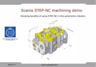
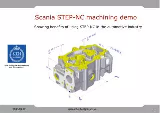
Scania STEP-NC machining demo Showing benefits of using STEP-NC in the automotive industry
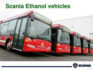
Scania cylinderhead • Typical powertrain component • 450 000 produced part during year 2007 • Machining features • Planer face • Hole • Machining operations • Planer mill • Drill • Ream
Work instructions • Creation and maintenance of work instructions is time consuming, even when having an more automated creation process. • Information given in these work instructions is geometry faces with tolerances related to used cutting tool. This information can also be represented in a STEP-NC model.
Work instructions as an view of STEP-NC data • Eliminating unnecessary information redundancy • Separation of representation and presentation • Fewer work instruction have to be created
Tool compensator adviser • Difficult to cover every possible scenario • The adviser utility is not part of STEP-NC standard, it’s a functionality utilizing the standard • Possible to implement for many more dimensional toleranced cases • Discussion on how to compensate deviation • Deflection, static and dynamic behavior • Axis motion delay • Individual cutting tool difference • Fixture placement error • Tool wear • …
What we have done • Implementation of GD&T representation, not presentation • Used recommended practices from CAx Implementor Forum and www.wikistep.org • GD&T harmonization between Application Protocols made our use of AP214e3 specification possible • Use of both Geometric and Dimensional tolerances along with Surface condition requirement • Together with STEP Tools Inc., developed presentation of relationship between tool and produced face with its tolerances
How we have done • Reading ARM, mapping tables and AIM sections • Created instantiation structure with Graphical Instance to represent tolerances for • Diameter Size Dimension (12 lines in file) • Linear Distance Dimension (16 lines in file) • Flatness Tolerance (6 lines in file) • Surface Texture (11 lines in file) • Reuse of created part 21 blocks that appended in end of STEP geometry part 21 file • Validated part 21 file with Express Engine • Developed a small Java application to automate append process. Manual instantiation of STEP models is a good learning lesson but also very time consuming. Use of STEP SDK is preferred for effective work
Java application • The purpose was to simplify writing tolerance information during STEP-NC demo preparation • Not proposed solution
Visualization format in STEP-manufacturing • ISO TC184 SC4, 54th Plenary meeting, Louisville USA Presentations of candidate solutions 2008-03-03 • U3D – ECMA TC43 • X3D – ISO/IEC JTC1/SC24 • 3D-XML – Dassault Systemes • JT Open • MPEG-4 – ISO/IEC JTC1/SC29 • COLLADA • Lattice 3D XVL • An visualization solution should include process data in addition to product data • Improves visual communication of manufacturing data
Visualization format in STEP-manufacturing • Scania cylinderhead AP214 p21 file size: 27660 kB • Scania cylinderhead Adobe 3D file size: 972 kB(Adobe support U3D and others candidate STEP visualization solutions)
Mikael Hedlind M.Sc., Ph.D Student KTH, Royal Institute of Technology Computer System for Design and Manufacturing Machinist background Employed at Scania since 1998 During 4 year worked with machining process optimizing and cutting tool evaluation at Scania. Magnus Lundgren B.Sc., Ph.D Student KTH, Royal Institute of Technology Computer System for Design and Manufacturing Machinist background Has worked as CNC-operator and manufacturing engineer for about 10 years before entering studies at KTH. Graduated for B.Sc. in 2001 and after that working with education at KTH in the area of manufacturing engineering.