Download
1 / 84
850 likes | 1.02k Views
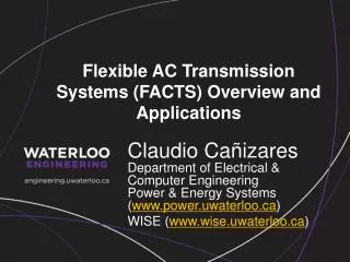
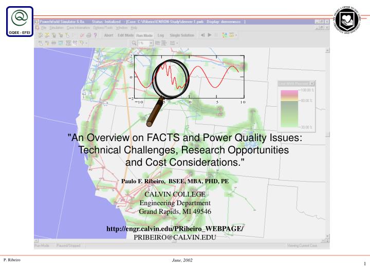
"An Overview on FACTS and Power Quality Issues: Technical Challenges, Research Opportunities and Cost Considerations.". Paulo F. Ribeiro, BSEE, MBA, PHD, PE CALVIN COLLEGE Engineering Department Grand Rapids, MI 49546 http://engr.calvin.edu/PRibeiro_WEBPAGE/ PRIBEIRO@CALVIN.EDU. FACTS

E N D
"An Overview on FACTS and Power Quality Issues: Technical Challenges, Research Opportunities and Cost Considerations." Paulo F. Ribeiro, BSEE, MBA, PHD, PE CALVIN COLLEGE Engineering Department Grand Rapids, MI 49546 http://engr.calvin.edu/PRibeiro_WEBPAGE/ PRIBEIRO@CALVIN.EDU
FACTS • The Concept • History / Background - Origin of FACTS, Opportunities, Trends • System Architectures and Limitations • Power Flow Control on AC Systems • Application Studies and Implementation • Basic Switching Devices • Systems Studies • AC Transmission Fundamentals • Voltage Source vs. Current Source • Voltage Sources • Static Var Compensator (SVC), STATCOM, TCSC, UPFC, SMES • System Studies (by EMTP, ATP, Saber, EDSA, EMTDC) • Systems Integration, Specification, Cost Considerations and Technology Trends • Impact of FACTS in interconnected networks • Market Assessment, Deregulation and Predictions
Power Quality • Objectives - Motivation - Background • Limitation of Traditional Tools • Advanced Techniques: • · Wavelet Theory Making Waves • · Expert Systems To Sag or Not to Sag: This is The ? • · Fuzzy Logic Not Really a Harmonic Distortion • · Neural Networks Remembering Wave Signatures • · Genetic Algorithms Evolutionary Distortions • · Combining Techniques Power Quality Diagnostic System • Power Electronics Implementing Advanced Power • Concepts
The reason, therefore, that some intuitive minds are not mathematical is that they cannot at all turn their attention to the principles of mathematics. But the reason that mathematicians are not intuitive is that they do not see what is before them, and that, accustomed to the exact and plain principles of mathematics, and not reasoning till they have well inspected and arranged their principles, they are lost in matters of intuition where the principles do not allow of such arrangement. They are scarcely seen; they are felt rather than seen; there is the greatest difficulty in making them felt by those who do not of themselves perceive them. These principles are so fine and so numerous that a very delicate and very clear sense is needed to perceive them, and to judge rightly and justly when they are perceived, without for the most part being able to demonstrate them in order as in mathematics, because the principles are not known to us in the same way, and because it would be an endless matter to undertake it. We must see the matter at once, at one glance, and not by a process of reasoning, at least to a certain degree. 1660 PENSEES by Blaise Pascal
The Concept • A transmission system can carry power up to its thermal loading limits. But in practice the system has the following constraints: • -Transmission stability limits • -Voltage limits • -Loop flows • Transmission stability limits: limits of transmittable power with which a transmission system can ride through major faults in the system with its power transmission capability intact. • Voltage limits: limits of power transmission where the system voltage can be kept within permitted deviations from nominal. Voltage is governed by reactive power (Q). Q in its turn depends of the physical length of the transmission circuit as well as from the flow of active power. The longer the line and/or the heavier the flow of active power, the stronger will be the flow of reactive power, as a consequence of which the voltage will drop, until, at some critical level, the voltage collapses altogether. • Loop flows can be a problem as they are governed by the laws of nature which may not be coincident with the contracted path. This means that power which is to be sent from point ”A” to point ”B” in a grid will not necessarily take the shortest, direct route, but will go uncontrolled and fan out to take unwanted paths available in the grid.
The Concept • FACTS devices • FACTS are designed to remove such constraints and to meet planners´, investors´ and operators´ goals without their having to undertake major system additions. This offers ways of attaining an increase of power transmission capacity at optimum conditions, i.e. at maximum availability, minimum transmission losses, and minimum environmental impact. Plus, of course, at minimum investment cost and time expenditure. • The term ”FACTS” covers several power electronics based systems used for AC power transmission. Given the nature of power electronics equipment, FACTS solutions will be particularly justifiable in applications requiring one or more of the following qualities: • -Rapid dynamic response • -Ability for frequent variations in output • -Smoothly adjustable output. • Important applications in power transmission involving FACTS and Power Quality devices:SVC (Static Var Compensators), Fixed * as well as Thyristor-Controlled Series Capacitors (TCSC) and Statcom. Still others are PST (Phase-shifting Transformers), IPC (Interphase Power Controllers), UPFC (Universal Power Flow Controllers), and DVR (Dynamic Voltage Restorers).
History, Concepts, Background, and Issues • Origin of FACTS • -Oil Embargo of 1974 and 1979 • -Environmental Movement • -Magnetic Field Concerns • -Permit to build new transmission lines • -HVDC and SVCs • -EPRI FACTS Initiative (1988) • -Increase AC Power Transfer (GE and DOE Papers) • -The Need for Power semiconductors • Why we need transmission interconnection • -Pool power plants and load centers to minimize generation cost • -Important in a deregulated environment • Opportunities for FACTS • Increase power transfer capacity • SVC (Nebraska GE 1974, Minnesota Westinghouse 1975, Brazil Siemens 1985) • TCSC, UPFC AEP 1999 • Trends • -Generation is not being built • -Power sales/purchases are being
System Architectures and Limitations System Architecture Radial, interconnected areas, complex network Power Flow in an AC System Power Flow in Parallel and Meshed Paths Transmission Limitations Steady-State (angular stability, thermal limits, voltage limits) Stability Issues (transient, dynamic, voltage and SSR) System Issues (Post contingency conditions, loop flows, short-circuit levels) Power Flow and Dynamic Stability Considerations Controllable Parameters Basic FACTS Devices - Impact of Energy Storage
System Architectures and Limitations The relative importance of transmission interconnection Interconnections in a European type system are not very important because the system is built by providing generation close to the loads and therefore, transmission is mainly for emergency conditions. In the US,very large power plants far from the load centers were built to bring "coal or water by wire". Large plants provided the best solution - economy of scale. Also, seasonal power exchanges have been used to the economic advantage of the consumers. Newer generation technologies favor smaller plants which can be located close to the loads and therefore, reduces the need for transmission. Also, if distributed generation takes off, then generation will be much closer to the loads which would lessen the need for transmission even further. However, for major market players, once the plant is built, the transmission system is the only way to bring power to the consumer that is willing to pay the most for the power. That is, without transmission, we will not get a well functioning competitive market for power.
Radial Parallel Meshed Power Flow Control on AC Systems Power Flow in Parallel Paths Power Flow in a Meshed Systems What limits the loading capability? Power Flow and Dynamic Considerations
50% Series Compensation Power Flow Control on AC Systems Relative Importance of Controllable Parameters Control of X can provide current control When angle is large X can provide power control Injecting voltage in series and perpendicular to the current flow, can increase or decrease
FACTS Applications and Implementations Transmission Transfer Capacity Enhancement Steady State Issues Voltage Limits Thermal Limits Angular Stability Limits Loop Flows Dynamic Issues Transient Stability Damping Power Swings Post-Contingency Voltage Control Voltage Stability Subsynchronous Res. Traditional Solutions Breaking Resistors Load Shedding Advanced Solutions FACTS Energy Storage Fixed Compensation Transmission Link Enhanced Power Transfer and Stability Line Reconfiguration Better Protection SVC STATCOM TCSC, SSSC UPFC FACTS Devices Increased Inertia
FACTS Devices • Shunt Connected • Static VAR Compensator (SVC) • Static Synchronous Compensator (STATCOM) • Static Synchronous Generator - SSG • Battery Energy Storage System (BESS) • Superconducting Magnetic Energy Storage (SMES) • Combined Series and Series-Shunt Connected • Static Synchronous Series Controllers (SSSC) • Thyristor Controlled Phase-Shifting Transformer or • Phase Angle Regulator (PAR) • Interline Power Flow Controller (IPFC) • Thyristor Controlled Series Capacitor (TCSC) • Unified Power Flow Controller (UPFC) • Relative Importance of Different Types of Controllers • Shunt, Shunt-Serie Energy Storage Energy Storage
Power Electronics - Semiconductor Devices • Diodes • Transistors • IGBT • Thyristors • SCR, GTO, MTO, ETO, GCT, IGCT, MCT Devices Diode (pn Junction) Silicon Controlled Rectifier (SCR) Gate Turn-Off Thyristor (GTO) GE MOS Turn-Off Thyristor (MTO) SPCO Emitter Turn-Off Thyristor (ETO) Virginia Tech Integrated Gate-Commutated Thyristor (IGCT) Mitsubishi, ABB MOS-Controlled Thyristor (MCT) Victor Temple Insulated Gate Bipolar Transistor (IGBT)
Power Electronics - Semiconductor Devices • Principal Characteristics • Voltage and Current • Losses and Speed of Switching • Speed of Switching • Switching Losses • Gate-driver power and energy requirements • Parameter Trade-off • Power requirements for the gate • di/dt and dv/dt capability • turn-on and turn-off time • Uniformity • Quality of silicon wafers IGBT has pushed out the conventional GTO as IGBTs ratings go up. IGBTs - Low-switching losses, fast switching, current-limiting capability GTOs - large gate-drive requirements, slow-switching, high-switching losses IGBTs (higher forward voltage drop)
Power Electronics - Semiconductor Devices Decision-Making Matrix
Planing Studies • Evaluate the technical and economic benefits of a range of FACTS alternative solutions which may allow enhancement of power transfer across weak transmission links. Part I of this effort should concentrate on preliminary feasibility studies to assess the technical merits of alternative solutions to correct real and reactive power transfer ratings, system voltage profiles, operational effects on the network, equipment configurations, etc. • A - Load flow studies will be performed to establish steady-state ratings, and identify the appropriate locations for connection of alternative compensation devices. Load flow studies will be used to address the following: • System Criteria (maximum steady-state power transfers, short-term operating limits, etc.) • Controller Enhancements (controller types, ratings, sensitivities, etc.) • Controller Losses (based on operating points and duration) • System Losses (system losses base on controller operating point and duration) • Overvoltsages ((steady-state and short-term voltage insulation requirements) • Compare technical and economic benefits of alternatives • Identify interconnection points • Identify critical system contingencies • Establish power transfer capability of the transmission system • Confirm that reliability criteria can be met • Identify the cost of capital of equipment and losses • Identify steady-state and dynamic characteristics of FACTS controllers • Stability Studies IEEE
System data and configuration Identify Transmission Systems - Provide System data and Configuration Load Flow (P,Q, V, q) System operat. limits Outages and load transfer Generator data Induction motor data Perform Load Flow (P,Q, V, q) System operat. limits Outages and load transfer Transient Stability (P,Q, V, q, time) Fault data Voltage Reg. Data (AVR) Identify and Size Transfer Enhancement Solutions Devices System changes Governor data Perform Economic Analysis Dynamic Stability (P,Q, V, q, w, time) Load Shedding Relay data IEEE System Studies
E1 / 1 P&Q I E2 . sin() (E1 - E2 . cos() X E1 E1 - E2 E2 . cos() P1 = E1 . Ip1 E1 . sin () Ip1 = E2 sin() / X I E1 . Cos () E2 Iq1 = (E1 - E2 . cos() / X (E2 - E1 . cos() AC Transmission Fundamentals E2 / 2
AC Transmission Fundamentals Active component of the current flow at E1 Ip1 = (E2 . sin ()) / X Reactive component of the current flow at E1 Iq1 = (E1 - E2 . cos ())/X Active Power at the E1 end P1 = E1 (E2 . sin ())/X Reactive Power at the E1 end Q1 = E1(E1 - E2 . cos ()) / X
P&Q E1 / 1 I X P1 = k1.E1 (E2 . sin (/k2))/X Q / V E1 E1 - E2 I E2 Regulating end bus voltage mostly change reactive power - Compensating at an intermediate point between buses can significantly impact power flow AC Transmission Fundamentals (Voltage - Shunt Control) E2 / 2 P1 = E1 (E2 . sin ())/X
AC Transmission Fundamentals (Voltage-Series Injection) E2 / 2 P&Q E1 / 1 I X Vinj Injected Voltage E1 P1 = E1 . E2 . sin () / (X - Vinj / I) E1 - E2 I E2 Injecting Voltage in series with the line mostly change real power
AC Transmission Fundamentals (Series Compensation) E2 / 2 P&Q E1 / 1 I X Changes in X will increase or decrease real power flow for a fixed angle or change angle for a fixed power flow. Alternatively, the reactive power flow will change with the change of X. Adjustments on the bus voltage have little impact on the real power flow. Vc Vx I P1 = E1 . E2 . sin () / (X - Xc) Vr Vs Vseff = Vs + Vc Real Power Angle Curve Xeff = X - Xc Vx Vc Power Transfer Vr Vxo Vs Vseff I Phase Angle
Injected Voltage E1 E1 - E2 I E2 AC Transmission Fundamentals (Voltage-Series and Shunt Comp.) E2 / 2 P&Q E1 / 1 I X P Integrated voltage series injection and bus voltage regulation (unified) will directly increase or decrease real and reactive power flow.
with VAR compensation (ideal midpoint) Q / V Maximum Power Transfer Amargin A2 no compensation A1 1 2 3 crit Phase Angle AC Transmission Fundamentals (Stability Margin) Improvement of Transient Stability With FACTS Compensation Equal Area Criteria 1 - prior to fault A1 = Acceleration Energy A2 = Deceleration Energy 2 - fault cleared 3 - equal area Therefore, FACTS compensation can increase power transfer without reducing the stability margin 3 >crit - loss of synchronism
Voltage Source Converters Basic 6-Pulse, 2-level, Voltage-Source Converter
Voltage Source Converters 2, 3, 5-level, VSC Waveforms
Voltage Source Converters Voltage-Source Converter Bridges
Voltage Source Converters Output voltage control of a two-level VSC
Voltage Source Converters Output voltage control of a three-level VSC
Voltage Source Converters Multi-pulse VSC with wave-forming magnetic circuits
FACTS Technology - Possible Benefits • Control of power flow as ordered. Increase the loading capability of lines to their thermal capabilities, including short term and seasonal. • Increase the system security through raising the transient stability limit, limiting short-circuit currents and overloads, managing cascading blackouts and damping electromechanical oscillations of power systems and machines. • Provide secure tie lines connections to neighboring utilities and regions thereby decreasing overall generation reserve requirements on both sides. • Provide greater flexibility in siting new generation. • Reduce reactive power flows, thus allowing the lines to carry more active power. • Reduce loop flows. • Increase utilization of lowest cost generation.
FACTS and HVDC: Complimentary Solutions HVDC Independent frequency and control Lower line costs Power control, voltage control, stability control FACTS Power control, voltage control, stability control Installed Costs (millions of dollars) Throughput MW HVDC 2 Terminals FACTS 2000 MW $ 40-50 M $ 5-10 M 500 MW $ 75-100M $ 10-20M 1000 MW $120-170M $ 20-30M 2000 MW $200-300M $ 30-50M (*)Hingorani/Gyugyi
FACTS and HVDC: Complimentary Solutions HVDC Projects: Applications Submarine cable Long distance overhead transmission Underground Transmission Connecting AC systems of different or incompatible frequencies • Large market potential for FACTS is within the ac system on a value-added basis, where: • The existing steady-state phase angle between bus nodes is reasonable • The cost of a FACTS device solution is lower than HVDC or other alternatives • The required FACTS controller capacity is less than 100% of the transmission throughput rating
FACTS Implementation - STATCOM E2 / 2 E1 / 1 P&Q I X Regulating Bus Voltage Can Affect Power Flow Indirectly / Dynamically P1 = E1 (E2 . sin ())/X
FACTS Implementation - TCSC E2 / 2 E1 / 1 P&Q X Line Impedance Compensation Can Control Power Flow Continuously P1 = E1 (E2 . sin ()) / Xeff Xeff = X- Xc The alternative solutions need to be distributed; often series compensation has to be installed in several places along a line but many of the other alternatives would put both voltage support and power flow control in the same location. This may not be useful. For instance, if voltage support were needed at the midpoint of a line, an IPFC would not be very useful at that spot. TCSC for damping oscillations ...
Breaker MOV TCSC #2 TCSC #3 TCSC #4 TCSC #5 TCSC #6 X TCSC module #1 Slatt TCSC FACTS Implementation - TCSC
Damping Circuit Damping Circuit Breaker Breaker MOV MOV MOV 40 Ω 55 Ω X X TCSC 15 to 60 Ω Kayenta TCSC FACTS Implementation - TCSC
FACTS Implementation - SSSC E2 / 2 P&Q E1 / 1 I X P1 = E1 (E2 . sin ()) / Xeff Xeff = X - Vinj/I
FACTS Implementation - UPFC E2 / 2 P&Q E1 / 1 I X Regulating Bus Voltage and Injecting Voltage In Series With the Line Can Control Power Flow P1 = E1 (E2 . sin ()) / Xeff Xeff = X - Vinj / I Q1 = E1(E2 - E2 . cos ()) / X
Series Transformer Shunt Inverter Series Inverter Shunt Transformer Unified Power Flow Controller FACTS Implementation - UPFC
FACTS Implementation - STATCOM + Energy Storage E2 / 2 E1 / 1 P&Q I X Regulating Bus Voltage Plus Energy Storage Can Affect Power Flow Directly / Dynamically Plus Energy Storage
FACTS Implementation - SSSC + Energy Storage E2 / 2 P&Q E1 / 1 I X Voltage Injection in Series Plus Energy Storage Can Affect Power Flow Directly / Dynamically and sustain operation under fault conditions Plus Energy Storage
FACTS Implementation - UPFC + Energy Storage E2 / 2 P&Q E1 / 1 I X Regulating Bus Voltage + Injected Voltage + Energy Storage Can Control Power Flow Continuously, and Support Operation Under Severe Fault Conditions (enhanced performance) Plus Energy Storage
Series Inverter 1000μF Shunt Inverter 1000μF 1000μF 1000μF SMES Chopper and Coil Unified Power Flow Controller - SMES Interface FACTS Implementation - UPFC + Energy Storage
MOV UPFC Grounding SMES Chopper and Coil - Overvoltage Protection FACTS Implementation - UPFC + Energy Storage