Download
1 / 6
70 likes | 229 Views
4 BALL GYRO TORQUE & ANGULAR MOMENTUM MOTORCYCLE COUNTER-STEERING. J. Ronald Galli Weber State University. 4 BALL GYRO – SIMPLE EXPLANATION. PUSH. The masses behave as a spinning wheel with initial motion as shown, in the xy plane.

E N D
4 BALL GYRO TORQUE & ANGULAR MOMENTUM MOTORCYCLE COUNTER-STEERING J. Ronald Galli Weber State University
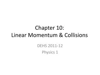
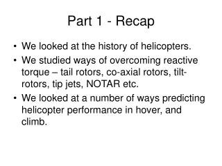
4 BALL GYRO – SIMPLE EXPLANATION PUSH • The masses behave as a spinning wheel with initial motion as shown, in the xy plane. • Next, the left hand pushes out away from the body (x direction) and the right hand pulls back toward the body. • Ball 1 is forced down as it moves left, toward the vertical yz plane. • This forces the left grip to move left and downward. • Similarly, the right grip is forced to move right and upward as ball 3 is forced up while moving right, toward the vertical yz plane. • Thus an initial torque about the y axis causes a twist about the x axis. 2 3 1 4 PULL Z Y X
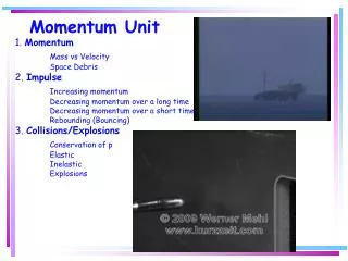
MOTORCYCLE TURN – SIMPLE EXPLANATION • Think of the front wheel of a motorcycle as consisting of 4 heavy balls attached to 4 strong “massless” rods and rolling, as shown, on a smooth “massless” rim. • Ball 1 spins to the top position while being forced to the left (negative x direction) by a push forward on the left handlebar, or a pull backward on the right handlebar. • This causes the wheel and the motorcycle to tilt downward to the left. • Now that the wheel and motorcycle are leaning to the left, a gravitation torque will turn the wheel to make a left turn. • This is like hanging the wheel (or 4 Ball Gyro) from a rope at the end of the right grip. Z Y X CONCLUSION: Pushing forward on the left grip or pulling back on the right grip will cause the two wheel motorcycle, at highway speeds, to turn TO THE LEFT! WOW!!
4 BALL GYRO • Copper pipe construction on bicycle axle hub • Four arms, each 10 inches long • Four balls – copper cups, each filled with one pound of lead • Steel handles • Total weight 7 pounds
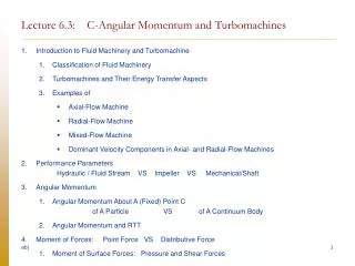
MOMENTS OF INERTIA 4 BALL GYRO WHEEL RADIUS R z z M y y M x x R M 4M M SPECIAL POSITIONS ON X AND Y AXES Iz = 4MR² Iz = Ix + Iy Ix = Iy = Iz⁄2 = 2MR² Iz = 4MR² Ix = Iy = 2MR² y M Thus the Moments of Inertia about the three principal axes are essentially the same for the 4 ball gyro as for the wheel of the same rim mass and radius. Therefore the equation τ = I will give the same dynamical result for the same torque applied under the same conditions. This would also be the same for a wheel with 4 additional masses attached to the rim. However Ix, Iy, andIzwould then each be increased accordingly (doubled for example, if all masses are as given herein). M y₂ R y₁ x α x₂ x₁ M M GENERAL POSITIONS - 90 degree separation Ix = 2My₁² + 2My₂² y₂ = x₁ Ix = 2M(x₁² + y₁²) = 2MR² Ix =Iy = 2MR² Iz = 4MR² z is out of page
FURTHER NOTES • Two Kinds of Force • Force of propulsion (forward or backward) – along the line of motion (motion speeds up or slows down) • Force of deflection for moving object – perpendicular to motion. Changes direction of motion. • Two Kinds of Torque (Twisting Force) • Torque of propulsion (forward or backward) – in the direction of spin (rotation speeds up or slows down) • Torque of deflection for spinning object – perpendicular to spin axis. Changes direction of spin axis. REFERENCES Ernest F. Barker, “Elementary Analysis of the Gyroscope”, Am. J. Phys. 28, 808-810 (1960) Harvey Kaplan and Andrew Hirsch, “Gyroscopic Motion: Show Me the Forces!” Phys. Teach. 52, 30-33 (2014) A demonstration wheel with 4 masses added is available from www.pasco.com