Download
1 / 51
520 likes | 811 Views
5. Electric Currents. Topic Outline. 5.1 Electric Potential Difference, Current and Resistance. Electric Potential Difference. Electric potential difference is the change in electric potential energy per unit charge V = voltage or potential difference, V

E N D
Electric Potential Difference • Electric potential difference is the change in electric potential energy per unit charge V = voltage or potential difference, V DEp = difference in electric potential energy, J q = charge, C • Voltage is a relative measure between two points
Electric Potential Difference • In circuits, we can consider the change in electric potential energy as a unit of charge moves through an energy supplier (e.g. a cell) or an energy user (e.g. a bulb) • In electric fields, we can consider the change in electric potential energy if a unit of charge was moved between two points in the electric field
The Electron Volt • In atomic and nuclear physics, it is often easier to use a smaller unit for energy • The electron volt is the amount of energy needed to move a charge of one electron through a potential difference of one volt DEp= qV • 1 eV = 1.6 x 10-19 x 1 • 1 eV = 1.6 x 10⁻¹⁹J
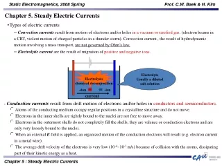
Electric Current • Conventional current is the movement (or ‘drift’) of positive charge towards a negative terminal • In solids, electrons move in metals and graphite, and ‘electron holes’ move in semiconductors • Positive and negative ions move in liquid metals and aqueous solutions • In gasses, the electrons and ions that move are often stripped of atoms by large potential differences • Electrical current is the amount of charge that moves past a point per second I = current, C.s-1 or Amperes or Amps, A (Amperes is a SI base unit) q = charge, Coulombs, C t = time, s
Resistance • Resistance is inversely related to how easily charges move through a substance • The resistance construction formula is: R = resistance of the wire, W r = resistivity of the substance, W.m l = length of the substance, m A = cross-sectional area, m2 • Some values of resistivity at 20°C are: • Silver 1.6 x 10⁻⁸Wm • Copper 1.7 x 10⁻⁸Wm • Nichrome 100 x 10-8Wm • Graphite 3-60 x 10-5Wm
Ohm’s Law • Georg Simon Ohm (1787-1854) studied resistance of different materials • He found that as the applied voltage across a material is increased, the current through the material increases with a constant ratio • This applies for many, but not all materials, when they are held at a constant temperature V = IR V = voltage, V I = current, A R = resistance, W
OhmicREsistors • Ohmic resistors obey Ohm’s Law • A graph of voltage versus current (at constant temperature) will give a straight line • The gradient of the line gives the resistance of the material • Metals obey Ohm’s Law across a large range of voltages if the metal is kept at a constant temperature.
Non-Ohmic Resistors • Non-ohmic resistors do not obey Ohm’s Law • As the temperature of tungsten wire (used in light-bulb filaments) increases, its resistance increases • Most metals have a higher resistance at higher temperatures
Non-Ohmic Resistors • A diode is a circuit component that allows current to travel in one direction only • The forward direction of a diode is the direction in which conventional current (positive charge) can move • A light emitting diode (LED)is a diode that emits light when current is passing through it
Non-Ohmic Resistors • A thermistor is made out of a semiconductor material, and its resistance decreases with temperature • Thermistors can be used to detect changes in temperature
Non-Ohmic Resistors • The resistance of a light dependent resistor (LDR) depends on the amount of light shining on it • LDRs can be used to detect light intensity
Electric Power • Power is the rate at which energy is converted from one form to another • In electrical circuits, the power dissipated by a resistor is given by: P = VI • This can be derived from the general formula for power P = DEp/t • Since V = DEp/q and I = q/t, P = Vq/(q/I) P = VI P = power, J.s-1 or Watts, W V = voltage, V I = current, A
Electromotive Force • Electromotive force(e.m.f.) is an historical term for the electrical energy supplied per unit charge • It is not a force (as the name suggests), but is measured in volts
Internal Resistance of a Cell • An electric cell supplies electrical energy to a circuit, and so has an e.m.f • An electric cell also has some resistance to electrical current, and so can be modelled by an e.m.f. and a resistor in series
Internal Resistance of a cell • The voltage across the terminals of the cell (the terminal voltage) is the e.m.f. minus the voltage lost across the internal resistance of the cell V = e - rI V = voltage across the terminals of the cell, V e = electromotive force (e.m.f.) of the cell (the chemical energy converted to electrical energy when a unit charge passes through the cell), V r = internal resistance of the cell, W I = current through the cell, A
Circuit Diagrams • Electric circuits have an energy supplier, an energy user, and a completed conducting pathway • Circuit diagrams need to have: • clear, ruled lines • connected lines (no gaps)
Resistors in Series & Parallel • Series Circuits • Resistors in a series circuit are arranged one after the other on a single loop of the circuit • The current is the same everywhere in the circuit; A1= A2 = A3 • The voltages across each electricity user add to the voltage across the supplier; V1 = V2 + V3 • Parallel Circuits • Resistors in a parallel circuit are arranged on separate branches of the circuit. • The currents in the branched part of the circuit add to give the current in the un-branched part of the circuit; A1 = A2 + A3 • The voltage across each branch of the circuit is the same; V1 = V2 = V3
Ammeters & Voltmeters • A galvanometeris a sensitive instrument that detects current • The D’Arsonval galvanometer consists of a coil of wire and a permanent magnet; when current passes through the coil, it moves; the deflection of the coil is proportional to the current
Ammeters & Voltmeters • To make an ammeter, put a resistor (a shunt) in parallel with a galvanometer • An ideal ammeter has no resistance so no electrical energy is dissipated through it • Ammeters are connected in series with the circuit • To make a voltmeter, put a resistor (a multiplier) in series with a galvanometer • An ideal voltmeter has infinite resistance so no electrical energy is dissipated through it • Voltmeters are connected in parallel with the circuit
The Potential Divider • A potential divider is used to control how much of the supply voltage goes to a component • The volume control on a stereo is a variable voltage divider
The Light-Dependent Resistor • The resistance of a light-dependant resistor (LDR) depends on the light intensity shining on it • An increase in light causes a decrease in resistance • If a LDR is put in the position of the top resistor of the potential divider, an increase in light intensity will decrease the voltage across the LDR and so increase the output voltage • If a LDR is put in the position of the lower resistor of the potential divider, an increase in light intensity will decrease the voltage across the LDR and the output • Uses of LDRs include camera light detectors and the controls of street lights
The Thermistor • The resistance of a thermistor depends on its temperature • In a negative temperature coefficient(NTC) thermistor, an increase in temperature causes a decrease in resistance • In a positive temperature coefficient(PTC) thermistor, an increase in temperature causes a increase in resistance • Uses of thermistors include electronic thermometers and controls of heating systems
The Strain Gauge • The resistance of a strain gauge depends on the amount of extension or compression of the device
The Transistor • A transistor amplifies small currents into larger currents • It has three leads (base, collector, emitter) • A small current comes in through the base, it is boosted by a larger current that comes in through the collector, and the large current leaves the transistor through the emitter
The Voltage Rectifier • A voltage rectifier uses diodes to ensure current from an alternating current (AC) source only flows in one direction
Electric Charge • An electrical charge (Q) can be positive or negative • Like charges repel, unlike charges attract • Charge is measured in Coulombs, C • Charge is conserved, i.e. in a closed system, the total amount of charge remains constant • Charge is quantised, i.e. the charge on any object must be a multiple of 1.6 x 10⁻¹⁹ C (the magnitude of the charge on an electron) • Friction can be used to transfer charges from one object to another, e.g. when polythene is rubbed with wool it becomes negatively charged, when cellulose acetate is rubbed with wool it becomes positively charged
Conductors & Insulators • Conductors transport charges freely • Charges rapidly distribute over the surface of a conductor • Graphite and all metals are good electrical conductors • Insulators do not readily transport charge • Charges on an insulator tend to stay where they are put • Plastics and ceramics are good insulators • Both conductors and insulators can store charge • Because Earth is so large, it can be considered an infinite ‘sink’ for charges – charges spread out over its surface and it remains effectively uncharged • The symbol for an electrical earth is
Charging an Electroscope • An electroscope is a device that demonstrates the presence of electric charge • A charged electroscope can be used to show the polarity of other charged objects • An electroscope can be charged by contact or by induction
Coulomb’s Law • Coulomb’s Law gives the force between two point charges • It is similar to Newton’s Law of gravity, except that the force can be attractive or repulsive • The force between the charges is equal and opposite • Use vector addition to work out the net force when there are multiple charges FE= electrostatic force, N k = Coulomb constant, 9.0 x 10⁹ N.m2.C-2 Q = charge, C r = distance between charges, m • Worksheet: Coulomb’s Law
Electric Fields • An electric field is a region of space where a charge will experience a force (cf. a gravitational field is a region of space where a mass will experience a force) • Electric field lines: • go from positive to negative • don’t cross • how close the lines are indicates how strong the electric field is E = electric field strength, N.C-1 F = force on a charge, N q = charge, C • Worksheet: Electric Fields
Electric Field of a Point Charge • Substituting FE = kQ1Q2 r2 into E = F/q, we get: E = kQ1Q2 ÷ q r2 E = the electric field due to a point charge, N.C-1 k = Coulomb’s constant, 9.0 x 10⁹ q = point charge, C r = distance from the charge, m • Worksheet: Electric Field of a Point Charge
Uniform Electric Fields • A uniform electric fieldhas a constant strength and direction • If a voltage is applied across two metal plates that are facing each other, an electric field is formed between the two plates E = electric field strength, N.C-1 (or V.m-1) V = voltage difference between the plates, V d = distance between the plates, m • Worksheet: Uniform Electric fields
Magnetic Fields • A magnetic field is a region of space where a magnetic force can be detected • Like poles repel, unlike poles attract • Magnetic field lines go from North to South • Magnetic fields exist around • magnetised objects, e.g. a bar magnet • conductors carrying a current
Magnetic Field around a Current-Carrying Wire • The direction of the magnetic field around a current-carrying wire is given by the right-hand thumb rule
Magnetic Field around a Current-Carrying Wire • The strength of the magnetic field around a current-carrying wire is: B = magnetic field strength, Tesla, T m0 = permeability of free space = 1.257 x 10⁻⁶ T.m.A-1 I = current, A r = distance from the wire, m
Magnetic Field in A Solenoid • A solenoid is a coil of wire • When current is passed through a solenoid, the magnetic field around each bit of the wire adds to give an overall magnetic field • The magnetic field around a solenoid is similar to the magnetic field around a bar magnet • The direction of the magnetic field is given by the right-hand thumb rule • curled fingers = direction of conventional current through the wires • thumb = direction of magnetic field
Magnetic Field in A Solenoid • The magnetic field in a solenoid is increased by: • increasing the number of coils per meter • increasing the current • changing the substance in the core of the solenoid (i.e. inserting iron into the core) B = m0mrnI B = magnetic field, T m0= permeability of free space = 1.26 x 10⁻⁶ T.m.A-1 mr = relative magnetic permeability of the substance in the core n = number of coils per metre I = current, A
Force on a Current- Carrying Wire • The direction of the force on a current-carrying wire is given by the right-hand slap rule • This force occurs because the stationary magnetic field and the magnetic field around the current-carrying wire interact • The magnetic force experienced by a current-carrying wire in a magnetic field is: F = BIL F = force on the current-carrying wire, N B = magnetic field strength, T I = current through the wire, A L = length of the wire in the magnetic field, m
Force on a Current- Carrying Wire • The equation F = B IL only applies when the current-carrying wire is at right angles to the magnetic field • If the wire is not at right angles to the field, we have to consider the equivalent length of the wire that is at right angles to the field F = BILsinq
Force on a Moving Charge • The direction of the magnetic force experienced by a charge moving in an electric field is also given by the right-hand slap rule • fingers = magnetic field • thumb = direction positive charge is moving in • slap = force on the charge • The magnetic force experienced by the charge is: F = Bqv F = force on the current-carrying wire, N B = magnetic field strength, T q = charge, C v = velocity, m.s-1
Force Between Two Current-Carrying Wires • If two current-carrying wires run parallel to each other, they exert an equal and opposite force on each other because the magnetic field of each wire exerts a force on the other • The magnitude of the force depends on the current in each of the wires and how far apart the wires are • If the two wires are carrying current in the same direction, the wires attract • If the two wires are carrying current in opposite directions, the wires repel F/l = force per meter, N.m-1 m0 = permeability of free space = 1.26 x 10⁻⁶ T.m.A-1 I1 = current in the first wire, A I2 = current in the second wire, A r = radius between the wires, m