Download
1 / 40
420 likes | 842 Views
Scope for Daikin Fan Coil Thermostats / Controlers. RAB. RDF. Fan Coil Control equipment. Room temperatur controllers. Additional sensor. Actuators & valves. RAB.. – Mechanic temperature controllers. Fan coil temperature controller RAB…. RAB10.1 Application. Roomtemperature control

E N D
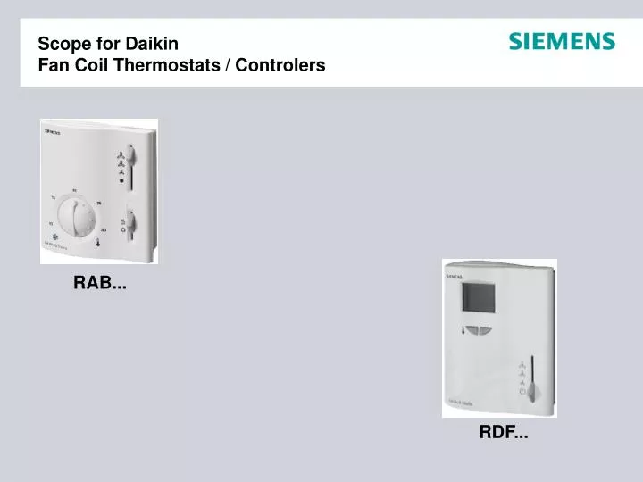
Scope for DaikinFan Coil Thermostats / Controlers RAB... RDF...
Fan CoilControl equipment Room temperatur controllers Additional sensor Actuators & valves
RAB10.1Application • Roomtemperature control • with roomthermostat heating / cooling • for 2-pipe fan coils • with 3-speed fan (AC250V) • with on-off valve • in • Residential buildings • Commercial buildings • Light industrial buildings
RAB10.1Electric connection diagram N1 Room thermostat RAB10.1 L Switching voltage AC250V N Neutral conductor M1 3-speed fanQ123 Control output “Fan speed” I-II-III AC250V / max. 6(2)A D Thermal valve or zone valveY Control output "Valve actuator", AC250V / 0,2...6(2)A Screw terminals for 2x 1,5mm² or 1x 2,5mm² (min 0,5mm²)
RAB30Application • Roomtemperature control • with roomthermostat heating / cooling • for 4-pipe fan coils • with 3-speed fan (AC250V) • with on-off valves • in • Residential buildings • Commercial buildings • Light industrial buildings
RAB30Electric connection diagram No supply for the thermostat required(gas filled diaphragm system) N1 Room thermostat RAB30.1 L Switching voltage AC250V N Neutral conductor M1 3-speed fan Q123 Control output “Fan speed” I-II-III AC250V / max. 6(2)A D1 Thermal valve or zone valve “Heating” Y1 Control output "Valve actuator", AC250V / 0,2...6(2)A D2 Thermal valve or zone valve “Cooling” Y2 Control output "Valve actuator", AC250V / 0,2...6(2)A Screw terminals for 2x 1,5mm² or 1x 2,5mm² (min 0,5mm²)
RAB…Temperature control • Temperature setpoint adjustment • with the setpoint setting knob (8…30°C) • The setpoint setting range can be limittedmechanically under the cover. Setpoint setting knob
RAB…Temperature control • Function diagram heating • Function diagram cooling T Room temperature SD Switching differential fix <= 1K W Room temperature setpoint 8…30°C Y Valve output signal AC 250V / 50 or 60 Hz 0,2…6(2) A
RAB…Operating modes • Operating mode adjustment • with the operating mode selector • Ventilation • fan operates at the selected speed • no heating / no cooling (Y contact open) • Heating • fan operates at the selected speed • Y contact is controlled by heating function • Cooling • fan operates at the selected speed • Y contact is controlled by cooling function Operating mode selector
RAB…Fan speed • Fan speed adjustment • with the fan speed selector • Manually • by means of 3-speed fan selector • for continous operation (jumper to SR1) • Automatically • by switching to the selected fan speed • when Y contact is „on“ (jumper to SR2) Fan speed selector
RAB…Dimensions, colour • Dimensions • Room thermostat Base plate • Colour • White - RAL 9003
RAB…Installation • The thermostat must be mounted on a flat wall.
X X X ! General aspectsMounting of room temperature controllers • The thermostat should be located where the room temperature can be acquired as accurately as possible, without getting adversely affected by direkt solar radiation or other heat or refrigeration sources. • Only authorized personal may open the unit to perform service (Caution: 250V!) The unit must be isolated from the mains supply before opening. Not on outside walls, into furniture, behind curtains, near windows!
RDF10Application • Room / return air temperature control • roomthermostat heating & cooling • for 2-pipe fan coils • with automatic change over sensor • with 3-speed fan (AC250V) • with on-off valve • with optional return air / room sensor • in • Residential buildings • Commercial buildings • Light industrial buildings
RDF10Connection diagram N1 Room temperatur controller RDF10 B1 Return air temp. sensor QAH11.1 or room temperature Sensor QAA32 B2 Change over temp. sensor QAH11.1 with mounting kit ARG86.2 S1 External operating mode switch M1 3-speed fanQ123 Control output “Fan speed” I-II-III AC250V / max. 6(4)A Y1 Heating / cooling valveY11 Control output “heating/cooling valve” AC250V / max. 5(3)A L Switching voltage AC250VN Neutral conductor SELV Screw terminals for 2x 1,5mm² or 1x 2,5mm² (min 0,5mm²)
RDF30Application • Room / return air temperature control • roomthermostat heating & cooling • for 4-pipe fan coils • with 3-speed fan (AC250V) • with on-off valve • with optional return air / room sensor • in • Residential buildings • Commercial buildings • Light industrial buildings
RDF30Connection diagram N1 Room temperatur controller RDF30 B1 Return air temp. sensor QAH11.1 or room temperature Sensor QAA32 S1 External operating mode switch M1 3-speed fanQ123 Control output “Fan speed” I-II-III AC250V / max. 6(4)A Y1 Heating valveY11 Control output “heating valve”Y2 Heating valveY21 Control output “cooling valve” AC250V / max. 5(3)A L Switching voltage AC250VN Neutral conductor SELV Screw terminals for 2x 1,5mm² or 1x 2,5mm² (min 0,5mm²)
RDF10Heating/cooling changeover (S1) • Contact open = heating mode • Contact closed = cooling mode • Automatic change over h/c - with sensor QAH11.1 • and ARG86.3 mounting set • - with external contact (suited for mains voltage)
RDF10Changeover sensor - QAH11.1 + ARG86.3 ARG86.3 ARG86.3 12..16mm
RDF10Heating/cooling (h/c) changover - setpoints • Purging function: the valve is opened for 1…5 minutes (adjustable with ) at 2-hour intervals during off hours.Ensures the correct acquisition of the medium temperature - even if the 2-port valve is closed for a longer period of time. • Highly recommended, if changeover sensor is used.
RDF..Changing the control parameters • Set operating mode selector to “Standby” • Press the + and – buttons simultaneously for a min. of 3 and a max. of 5 seconds. Release them and within 2 seconds, press the + button again for 3 seconds. The display will show “P01”. • Select the required parameter by repeatedly pressing the + or – button: • Press the + and – buttons simultaneously, the current value of the selected parameter appears, which can be changed by repeatedly pressing the + or – button. • By pressing buttons + and - simultaneously again or 5 seconds after the last press of a button, the last parameter will be displayed again. • If you wish to display and change additional parameters, repeat steps 3 through 5. • 10 seconds after the last display or setting, all changes will be stored. • Switch to normal operation with the operating mode selector. 3-5sec 0-2sec 3sec
Parameter number RDF..Commissioning - Setpoints
Parameter number RDF10Commissioning – Switching differential
Parameter number RDF30Commissioning - Switching differential, dead band
Parameter number RDF..Sensor calibration Difference (i. e.) = 1K 23.5 Sensor calibration +/- 3K
RDF…Dimensions, colour • Dimensions • Room thermostat Base plate • Colour • White - RAL 9003
RAB.. / RDF..Combinations with valves & actuators • STP21 • Electrothermic actuator for 230V • 2-point, A-AB normally closed • STA21 • Electrothermic actuator for 230V • 2-point, A-AB normally open ST.21 + VVP47… ST.21 + VXP47… ST.21 + VMP47…
RAB.. / RDF..Valves overview ALG132 (DN10)ALG142 (DN15)ALG202 (DN20) Material: ALG132, ALG142 – brass ALG202 – malleable cast iron ALG133 (DN10)ALG143 (DN15)ALG203 (DN20) Material: ALG133, ALG143 – brass ALG203 – malleable cast iron
Sales arguments • Unique excellence in innovation & design • Worldwide sales support and service • Very competitive solution for basic requirements • Easy to use user interface, ideal for rooms with changing occupancy • Outstanding look and feel from one of the world’s most successful industry design companies • Full range of room thermostats • Fan release function for more comfort and energy saving