Download
1 / 19
270 likes | 508 Views
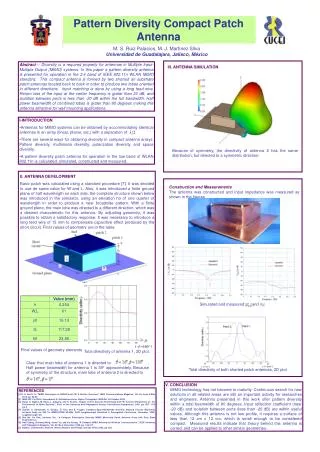
Pattern Synthesis and Antenna Receiver Design for Passive Coherent Location. Gunther Lange Radar Remote Sensing Group University of Cape Town Supervisor: Professor Mike Inggs. Presentation Outline. Brief overview of passive coherent location (PCL) Motivation for study

E N D
Pattern Synthesis and Antenna Receiver Design for Passive Coherent Location Gunther Lange Radar Remote Sensing Group University of Cape Town Supervisor: Professor Mike Inggs
Presentation Outline • Brief overview of passive coherent location (PCL) • Motivation for study • Objectives and Methodology • Signal environment of the Cape Town region • Geometry of the problem • Discussion of possible transmitters for target illumination • Pattern synthesis of an antenna array • Beam forming and null placement • Simulation of pattern synthesis method • Work in progress • Conclusion © CSIR 2006 www.csir.co.za
Overview of Passive Coherent Location • Exploit ambient radio signals • Detect reflections off targets using signals from Tx1 • Reference signal required for signal processing • Suppress interference • Direct signal (Null 1) • Jamming signal (Null 2) • Null placement is vital for electronic countermeasures • Receiver forms a single node of a netted radar system © CSIR 2006 www.csir.co.za
Motivation4 • PCL would exploit ambient radio signal provided by the existing broadcasting infrastructure, the “illuminators of opportunity”. • PCL can be operated covertly. i.e. The receiver is not easily detected since it is only monitoring the ambient signals in the environment. • Effective null placement would be essential for the suppression of jamming signals. • A netted or multistatic PCL system can be used for counter stealth. • PCL is relatively inexpensive, mobile, versatile and suitable for rapid deployment. • The application of a PCL system would enhance air security. © CSIR 2006 www.csir.co.za
Objectives and Methodology The core objective is to develop a single static PCL receiver node at UCT which will be accomplished by: • Mapping the signal environment of the Cape Town region • Determine the most favourable transmitter and its broadcast signal for the “illuminator of opportunity”. • An investigation in methods of pattern synthesis of an antenna array • Steer beam in the direction of a moving target • Place nulls in the direction of strong interference • Construction and testing of receiver node © CSIR 2006 www.csir.co.za
Signal Environment of the Cape Town Region • A transmitter possessing the best characteristics of “illuminator of opportunity” is required • Transmitter list was provided by Sentech • Radio FM frequencies • Television VHF and UHF channels • Selection of transmitter was based on • Location • Illumination and beam width • Signal Strength © CSIR 2006 www.csir.co.za
Selection of Illuminating Transmitter • Location of Receiver • UCT Menzies • Location of Airport • Location of Constantiaberg transmitter • 70° beam width (red lines) • Illuminates section just north of runway • Airplanes from JHB usually approach runway from the north (green line) © CSIR 2006 www.csir.co.za
Selection of Signal Frequency • Each transmitter has multiple frequencies • FM radio to VHF and UHF TV • Selection based on direct reference signal strength • Friss equation • Physical antenna measurements • Simulation using AREPS3, a EM propagation tool • FM has greater signal strength © CSIR 2006 www.csir.co.za
Pattern Synthesis of an Antenna Array • The method of designing an array of antennas such that it yields an acceptable radiation pattern is known as pattern synthesis1. • Pattern synthesis in general refers to: • Beam forming which ensures maximum gain in the direction of the target. • Null placement for the suppression of interference. • Applying methods of pattern synthesis aids us in determining: • Configuration of the antenna array • Dimensions of the antenna array • Excitation distribution of the array elements © CSIR 2006 www.csir.co.za
Pattern Synthesis Methods • Pattern Synthesis methods can be split into three major categories1: • Beam shaping • Fourier • Narrow beam forming • Dolph-Tschebyscheff • Taylor • Binomial • Null placement • Schelkunoff © CSIR 2006 www.csir.co.za
Locations of Interferring Signals • The receiver system is located at UCT (Menzies) • Suppress the direct signal from Constantiaberg with Null 1 • At a bearing of 212° • Suppress a jamming signal with Null 2 • Place the hypothetical jammer at a bearing of 20° • Maintain main beam in the direction of the airport © CSIR 2006 www.csir.co.za
Schelkunoff Polynomial Method • Specify null postions and determine Schelkunoff polynomial zeros. • The subsequent coefficients of the Schelkunoff polynomial yield the element excitations • An array of 4 antenna elements will be used • The antenna array must be practically realisable • 4 elements make the array ~4.5m long at FM radio frequencies © CSIR 2006 www.csir.co.za
Schelkunoff FEKO Simulation • The antenna arrays are simulated with FEKO2, a powerful antenna modelling program • Begin with 4 hertzian dipoles • Point sources (near-isotrophic) • This would illustrate a best case scenario • Next look at 4 folded dipoles • Structurally more stable than simple half-wave dipoles • Similar pattern to half-wave dipoles © CSIR 2006 www.csir.co.za
Schelkunoff FEKO Simulation – Array Pattern Null 1 Direct Signal Constantiaberg Null 2 Jamming Interference Airport North © CSIR 2006 www.csir.co.za
Schelkunoff FEKO Simulation – Array Pattern Null 1 Direct Signal Constantiaberg Null 2 Jamming Interference Airport North © CSIR 2006 www.csir.co.za
Antenna Array Challenges Airport • Problem • Symmetrical Pattern about the array axis • Large back lobe • Solution • Addition of Reflectors and Directors • Increased complexity • In terms of application of synthesis methods Back lobe © CSIR 2006 www.csir.co.za
Work in Progress • Adding directors and reflectors creates a Yagi-Uda antenna • Yagi-Uda antennas as elements of an array • What synthesis method can be applied to yield • Beam forming • Null placement © CSIR 2006 www.csir.co.za
Conclusion • Investigating the signal environment and methods of pattern synthesis will form a good foundation for the development of a PCL receiver node. • Once the groundwork is in place construction of an antenna array and a PCL system node will begin. • The complete PCL system will eventually be able to: • Detect targets passively using FM radio signals • Steer nulls into desired directions to suppress interference • Form beams in the direction of targets © CSIR 2006 www.csir.co.za
References & Acknowledgments • 1 Constantine Balanis. Antenna Theory and Design 2006 • 2 http://www.feko.info/ • 3 http://areps.spawar.navy.mil/ • 4 University College London and the Passive Bistatic Radar • For their supervision and guidance Professor Mike Inggs and Yoann Paichard © CSIR 2006 www.csir.co.za