Download
1 / 43
430 likes | 500 Views
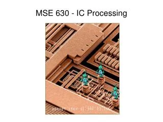
MSE-630 Week 3. Semiconductor Operation IC Fabrication Quantum Mechanics: Particle in a box. Junctions and Semiconductors Theories and practical devices. View of an Integrated Circuit. (a). (d). Al. (d). Si. (doped). 45 m m. 0.5 mm.

E N D
MSE-630 Week 3 Semiconductor Operation IC Fabrication Quantum Mechanics: Particle in a box
Junctions and Semiconductors Theories and practical devices
View of an Integrated Circuit (a) (d) Al (d) Si (doped) 45mm 0.5mm • A dot map showing location of Si (a semiconductor): -- Si shows up as light regions. (b) (c) • Scanning electron micrographs of an IC: • A dot map showing location of Al (a conductor): -- Al shows up as light regions. 3
Metallic and Semiconductor Junctions Each conductor has a unique quantity of energy that is required to free an electron. This energy is called the work function energy, qF. Values for qFfor various metals are given in the table below:
In figure A, two dissimilar metals are not in contact. When they come into contact as shown in B, their respective Fermi energies must equilibrate throughout. To do this, electrons transfer from B to the lower unfilled levels of A until the level of the electron “sea” in both metals is equal. This causes A to become negatively charged, and B to become positively charged. The resulting potential is called the contact potential (qVC) The Contact Potential, qVC, is equal to the difference in the respective work functions: qVC = EF(B)-EF(A), or qVC=qF(A)-qF(B)
Although a potential exists, no work can be extracted, because when we attach leads, (i.e., metal C) the sum of the work functions is zero: qFnet = q(FC-FA)+(FA-FB)+FB-FC)] = 0
If we join an “n” type region, which has excess negative charges, with a “p” type region, i.e. a “p-n” junction” a charged region develops a the interface: Electrons and holes recombine at the interface, depleting the available electrons in the n material making it more positive, and holes in the p material, making it more negative. This creates a built-in electric field that discourages further transfer across the interface.
Metallic and Semiconductor Junctions Each conductor has a unique quantity of energy that is required to free an electron. This energy is called the work function energy, qF. Values for qFfor various metals are given in the table below:
In figure A, two dissimilar metals are not in contact. When they come into contact as shown in B, their respective Fermi energies must equilibrate throughout. To do this, electrons transfer from B to the lower unfilled levels of A until the level of the electron “sea” in both metals is equal. This causes A to become negatively charged, and B to become positively charged. The resulting potential is called the contact potential (qVC) The Contact Potential, qVC, is equal to the difference in the respective work functions: qVC = EF(B)-EF(A), or qVC=qF(A)-qF(B)
Although a potential exists, no work can be extracted, because when we attach leads, (i.e., metal C) the sum of the work functions is zero: qFnet = q(FC-FA)+(FA-FB)+FB-FC)] = 0
Electron band diagrams are a way to visualize what happens at a p-n junction, using the following rules: • The Fermi level must be at the same level on both sides of the junction when there is no applied field • Far from the junctions, the materials inherent electrical structure exists • He bands are bent, or curved, where the built-in electric fields exist at the junction • A potential energy step, qVc, due to contact potential Vc, develops at the junction. It is equal in magnitude to EF(n)-EF(p) or, equivalently qF(p)-qF(n) • Externally applied electric potentials displace the relative positions of EF and the band edges by amounts over and above those produced by the above rules.
If we apply a “reverse bias”, as depicted in A above and in figure B on the left, the barrier at the junction increases to q(Vo+V), thus increasing the barrier to current flow. If we apply a forward bias, as in B above and C, left, we annihilate EHPs and have a positive current flow
If we join an “n” type region, which has excess negative charges, with a “p” type region, i.e. a “p-n” junction” a charged region develops a the interface: Electrons and holes recombine at the interface, depleting the available electrons in the n material making it more positive, and holes in the p material, making it more negative. This creates a built-in electric field that discourages further transfer across the interface.
p-n Rectifying Junction + - + - + + - - + - p-type - n-type + + + - + - - + - - + n-type - p-type + + - - + + - + - + - • Allows flow of electrons in one direction only (e.g., useful to convert alternating current to direct current). • Processing: diffuse P into one side of a B-doped crystal. p-type n-type -- No applied potential: no net current flow. -- Forward bias: carriers flow through p-type and n-type regions; holes and electrons recombine at p-n junction; current flows. -- Reverse bias: carriers flow away from p-n junction; junction region depleted of carriers; little current flow. 14
Properties of Rectifying Junction Forward biasing causes current to flow; reverse biasing causes it to stop flowing in a p-n junction. This can be represented in the junction equation: j = jR[exp (eV/kT)-1] V is positive for forward biasing, and negative for reverse biasing. jR is the reverse biased current 15
Tunnel Diodes Tunnel diodes act as oscillators. Current increases up to Vp, decreases between Vp and Vc, then increases beyond Vc As shown at left, the Fermi level exists in the conduction zone of the n-type material and the valence zone of the p-type material. When a biasing voltage is applied, the electrons jump, or “tunnel” across the forbidden gap at the junction. When Vp<V<Vc, the gap widens and tunneling becomes small. Then, when V>Vc, tunneling can begin again.
Zener diodes Zener diodes are used to regulate voltages in circuits. When the voltage becomes sufficiently large (10-1000V, depending on doping level), it reaches a “limiting” or “break down” voltage, and current is shunted to ground.
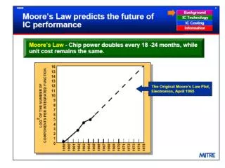
MOSFET Transistor Integrated Circuit Device Integrated circuits - state of the art ca. 50 nm line width ~ 1,000,000,000 components on chip chips formed one layer at a time • MOSFET (metal oxide semiconductor field effect transistor) 20
Current flow in a transistor vary with emitter voltage, Ve: I = Ioexp(Ve/B) Where Io and B are constants MOS-FET
Numerous transistors, resistors and electronic elements can be incorporated on a single wafer of semiconductor material, thus creating the integrated circuit
Thermocouples and other thermoelectric devices If opposite ends of a metal bar are maintained at different temperatures, electrons will flow from the hot end to the cold end. As electrons pile up at the cold end, it creates a net electromotive force, or Seebeck voltage, opposing further charge transfer. Seebeck voltage varies sensitively with temperature, and are 1000-fold larger in semiconductors than in metals. Using semiconductors used to measure changes in voltage are called thermistors, and can very accurately measure temperature
Other devices that measure temperature or have thermoelectric properties include thermocouples, Peltier effect and thermoelectric refrigerators. When metals with different work functions are joined, they generate a voltage that varies with temperature. Thermocouples accurately measure temperature by measuring this voltage difference. When current flows through a junction, heat may be generated or absorbed, depending on current polarity. This enables the design of electric refrigerators
Semiconductors are built in layers. • Each layer involves several steps: • Placing a film of light sensitive emulsion on the Si substrate • Covering the areas to be protected • Exposing to light • Removing exposed emulsion • Etching away exposed substrate • Removing mask • Depositing dopants • Diffusing dopants into substrate
Initial Steps: Forming an active region Photoresist is chemically removed in acid, or stripped in an O2 plasma After stripping photoresist, field oxide is grown. Field oxide provides insulation between adjacent junctions Si3N4 is etched away using an F-plasma: Si3dN4 + 12F → 3SiF4 + 2N2 Or removed in hot phosphoric acid
N and P wells are formed Photoresist mask is applied, and active ions implanted by ion bombardment. Typically, 150-200 keV accelerating energy After implantation, ions are diffused into substrate to form wells
After well formation, additional N and P layers are formed in respective N and P wells, then a layer of polysilicon is deposited. Polysilicon is electrically conductive and used for gate voltage connections.
Insulating layers of SiO2 are grown around the gate, followed by N or P bombardment for form the NMOS or PMOS source and drain regions. After forming gate, source and drain regions, Ti film is deposited by sputtering to act as electrical interconnect
Ti is reacted with N2 to form TiSi2 where it contacts silicon (black regions) or TiN elsewhere. Then, it is coated with photoresist and etched, followed by deposit of another insulating SiO2 layer. Another coat of photoresist followed by etching exposes gates for connections
A barrier region of TiN is applied, followed by thin-film application of W, which undergoes CMP to provide a flat surface with exposed contacts Finally, aluminum is sputtered on wafer, masked and plasma etched. Additional interconnect layers may be added the same way.
Wave-Particle Duality Photons In trying to explain black body radiation and thermoelectric effect, Max Planck and Albert Einstein developed theories that when put together led to the following principles. 1. Light is made up of particles called photons. • The energy of a photon is dependent only upon its frequency. E = hn = hc/l Where h is Planck’s constant (h = 6.626 x 10⁻³⁴ J-s). What this means is that if an object is giving off (or absorbing) light it is actually emitting (absorbing) photons. The energy of each photon is dependent only upon its frequency (or wavelength or color). In 1925, Louis DeBroglie hypothesized that if light, which everyone thought for so long was a wave, is a particle, then perhaps particles like the electron, proton, and neutron might have wave-like behaviors. In the same way that waves are described by their wavelength, particles can be described by their momentum, p p = mv where m is the mass of the particle and v is its velocity. We can relate the velocity of a wave-particle with its wavelength by equating Planck’s relationship for the energy of a photon with Einstein’s Law of Relativity: E = hn = hc/l E = mc2 If we equate these two equations we get a relationship between momentum (a particle property) and wavelength (a wave property) hc/l = mc2 = pc p = h/l Or by substituting mv for momentum we can wavelength of any object to its velocity and mass. l= h/mv
Element spectral lines were empirically described using the integer values of ‘n’ The only problem with these models is that they do not account for line splitting
Bohr Model of the Atom • Electrons are in stable circular orbits about the nucleus and do not decay • Electrons move to higher orbit by gaining energy (absorbing a photon of energy hn), or drop to a lower orbit, emitting a photon • Electron angular momentum, pq is an integer multiple of n, or pq = nh/2p
What was correct about Bohr’s Model: • Electrons reside in quantized energy levels. • The Bohr model accurately and quantitatively predicts the energy levels of one electron atoms. • What was incorrect about Bohr’s Model: • Electrons don’t orbit the nucleus in well defined circular orbits. • Fails to accurately predict the energy levels in multielectron atoms.
Heisenberg Uncertainty Principle Uncertainty Principle → It is not possible to precisely determine the momentum (hence the energy) and the position of a particle simultaneously. This is quantified in the mathematical expression: Dx Dp = h/4p Dx m Dv = h/4p where Dx represents the uncertainty in the position of the particle and Dp represents the uncertainty in the momentum of the particle (p = mv).
Results of Uncertainty Principle We cannot say where a particle (electron) is, only the probability of finding it at that particular place Quantum mechanics defines the functional relationships we can use to solve for properties such as position, momentum and energy, using a wave function, y
The Schrödinger Equation, Wave Functions and Hamiltonians In one dimension, we can describe the energy of a particle in terms of its wave function as: Writing y(x,t) as two separate variables, y(x)f(t), we get independent equations in terms of position and time:
The Hydrogen Atom We can solve the wave function for the Hydrogen atom by using spherical coordinates (r,q,f) and solving the independent wave equations using separation of variables: Y(r,q,f) = y(r)Q(q)F(f) This leads to three of the four quantum numbers: n,l,m and s