Download
1 / 14
280 likes | 2.66k Views
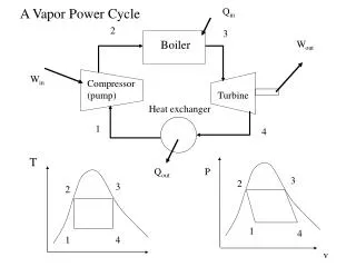
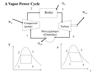
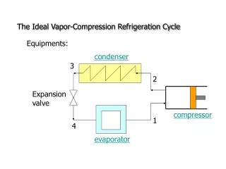
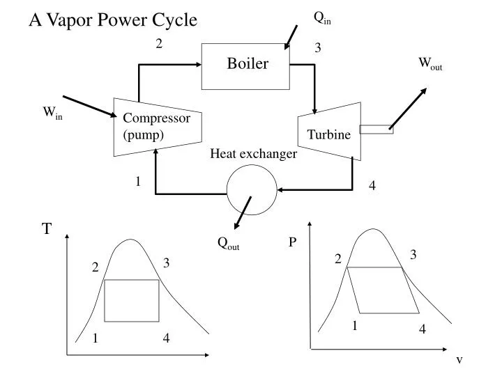
Q in. 2. 3. Boiler. W out. W in. Compressor (pump). Turbine. Heat exchanger. 1. 4. T. Q out. P. 3. 2. 3. 2. 1. 4. 1. 4. v. A Vapor Power Cycle. Optimization of a Vapor Power Plant. Objectives: design an optimal vapor power cycle use idealized Carnot cycle as the model;

E N D
Qin 2 3 Boiler Wout Win Compressor (pump) Turbine Heat exchanger 1 4 T Qout P 3 2 3 2 1 4 1 4 v A Vapor Power Cycle
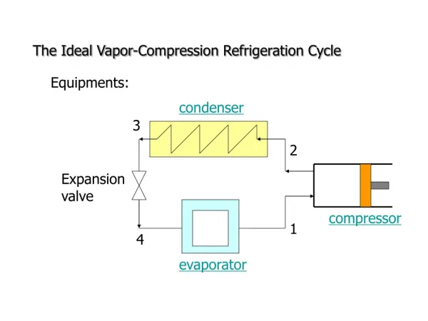
Optimization of a Vapor Power Plant • Objectives: design an optimal vapor power cycle • use idealized Carnot cycle as the model; • consider all theoretical and practical limitations and redesign the cycle accordingly Idealized Rankine cycle; • optimize the Rankine cycle using concepts of superheating, reheating and regeneration; • discussion concerning the increase of the efficiency of an idealized Rankine cycle. Carnot cycle 3 2 T T 3 2 4 (b) OR 1 (a) 1 4 s s
Practical Problems associated with Carnot Cycle Plant • Maximum temperature limitation for cycle (a). What is the maximum temperature in the cycle? • Isentropic expansion in a turbine from 3-4. What is the quality of the steam inside the turbine? Will high moisture content affect the operation of the turbine? • Isentropic compression process in a pump from 1-2. Can one design a condenser and transmission line system that precisely control the quality of the vapor in order to achieve an isentropic compression? Even we can, is it practical to handle two-phase flow (liquid + vapor) using such a system? • The latter two problems can be resolved by the use of cycle (b) from previous slide. However, the (b) cycle requires the compression(1-2)of liquid at a very high pressure (exceeding 22 MPa for a steam, how do I get this number from?) and that is not practical. Also, to maintain a constant temperature above the critical temperature is also difficult since the pressure will have to change continuously.
How about a modified cycle - A Rankine cycle 3 T • To avoid transporting and compressing two-phase fluid, we can try to condense all fluid exiting from the turbine into saturated liquid before compressed it by a pump. 2 4 1 s • when the saturated vapor enters the turbine, its temperature and pressure decrease and liquid droplets will form by condensation. These droplets can produce significant damages to the turbine blades due to corrosion and impact. One possible solution: superheating the vapor. It can also increase the thermal efficiency of the cycle.
3 2 1 4 Ideal Rankine Cycle • Energy analysis: steady flow process, no generation, neglect KE and PE changes for all four devices, • 0 = (net heat transfer in) - (net work out) + (net energy flow in) • 0 = (qin - qout) - (Wout - Win) + (hin - hout) • 1-2: Pump (q=0) • Wpump = h2 - h1 = v(P2-P1) • 2-3: Boiler (W=0) qin = h3 - h2 • 3-4: Turbine (q=0) Wout = h3 - h4 • 4-1: Condenser (W=0) qout = h4 - h1 T s Thermal efficiency h = Wnet/qin =1 - qout/qin = 1 - (h4-h1)/(h3-h2) Wnet = Wout - Win = (h3-h4) - (h2-h1)
Qin 2 3 Example Consider the Rankine power cycle as shown. Steam enters the turbine as 100% saturated vapor at 6 MPa and saturated liquid enters the pump at a pressure of 0.01 MPa. If the net power output of the cycle is 50 MW. Determine (a) the thermal efficiency, (b) the mass flow rate of the system, ( c) the rate of heat transfer into the boiler, (d) the mass flow rate of the cooling water from the condenser, in kg/s, if the cooling water enters at 20°C and exits at 40°C. Wout boiler Turbine Win pump condenser 1 4 Qout T 3 2 4 1 s
Solution • At the inlet of turbine, P3=6MPa, 100% saturated vapor x3=1, from saturated table A-5, h3=hg=2784.3(kJ/kg), s3=sg=5.89(kJ/kg K) • From 3-4, isentropic expansion: s3=s4=5.89 (kJ/kg K) • From 4-1, isothermal process, T4=T1=45.8°C (why?) • From table A-5, when T=45.8°C, sf4=0.6491, sfg4=7.5019, hf4=191.8, hfg4=2392.8 • x4 = (s4-sf4)/sfg4 = (5.89-0.6491)/7.5019 = 0.699 • h4 = hf4+x4* hfg4 = 191.8+0.699(2392.8) = 1864.4 (kJ/kg) • At the inlet of the pump: saturated liquid h1=hf1=191.8 • qout = h4-h1=1672.6(kJ/kg) • At the outlet of the pump: compressed liquid v2=v1=vf1=0.00101(m3/kg) • work input to pump Win = h2-h1 = v1 (P2-P1) = 0.00101(6000-10) = 6.05 • h2 = h1 + v1 (P2-P1) =191.8 + 6.05 = 197.85 (kJ/kg) • In the boiler, qin=h3-h2=2784.3-197.85=2586.5(kJ/kg)
Solution (cont.) • (a) The thermal efficiency h = 1-qout/qin= 1-1672.6/2586.5=0.353=35.3% • (b) Net work output dW/dt=50MW=(dm/dt)(Wout-Win)=(dm/dt)((h3-h4)-(h2-h1)) • mass flow rate (dm/dt)=50000/((2784.3- 1864.4 )-(197.85-191.8))=54.7(kg/s) • ( c) heat transfer into the boiler qin = (dm/dt)(h3-h2)=54.7(2586.5)=141.5(MW) • (d) Inside the condenser, the cooling water is being heated from the heat transfered from the condensing steam. • q cooling water = qout = (dm/dt)(h4-h1) = 54.7(1672.6) = 91.49 (MW) • (dm/dt)cooling water Cp (Tout - Tin) = q cooling water • C p, water = 4.177(kJ/kg K) • (dm/dt)cooling water = 91490/(4.177*(40-20)) = 1095.2 (kg/s) • Very large amount of cooling water is needed
3 T T 2 2 1 1 4 s s Thermal Efficiency • Thermal efficiency can be improved by • (a) Lowering the condensing pressure (lower condensing temperature, lower TL) • (b) Superheating the steam to higher temperature • ( c) Increasing the boiler pressure (increase boiler temperature, increase TH) ( c) increase pressure 3 T (b) Superheating 2 4 1 s Low quality, high moisture content (a) lower pressure(temp)
Reheating • The optimal way of increasing the boiler pressure but not increase the moisture content in the exiting vapor is to reheat the vapor after it exits from a first-stage turbine and redirect this reheated vapor into a second turbine. T high-P turbine 5 3 3 high-P turbine Low-P turbine low-P turbine boiler 4 4 5 2 6 1 6 2 pump 1 s condenser
Reheat Rankine Cycle • Reheating allows one to increase the boiler pressure without increasing the moisture content in the vapor exiting from the turbine. • By reheating, the averaged temperature of the vapor entering the turbine is increased, thus, it increases the thermal efficiency of the cycle. • Multistage reheating is possible but not practical. One major reason is because the vapor exiting will be superheated vapor at higher temperature, thus, decrease the thermal efficiency. Why? • Energy analysis: Heat transfer and work output both change qin = qprimary + qreheat = (h3-h2) + (h5-h4) Wout = Wturbine1 + Wturbine2 = (h3-h4) + (h5-h6)
Regeneration • From 2-2’, the temperature at 2 is very low, therefore, the heat addition process is at a lower temperature and therefore, the thermal efficiency is lower. Why? • Use regenerator to heat up the liquid (feedwater) leaving the pump before sending it to the boiler, therefore, increase the averaged temperature (efficiency as well) during heat addition in the boiler. higher temp heat addition Lower temp heat addition 5 3 T T Extract steam from turbine to provide heat source in the regenerator 2’ 4 6 2 3 2 7 1 4 1 s s Use regenerator to heat up the feedwater
Regenerative Cycle • Improve efficiency by increasing feedwater temperature before it enters the boiler. • Open feedwater: Mix steam with the feedwater in a mixing chamber. • Closed feedwater: No mixing. Open FWH 5 T 5 boiler 4 (y) 6 6 Open FWH 7 (y) (1-y) 2 (1-y) 3 3 2 4 Pump 2 7 1 s Pump 1 1 condenser
Regenerative Cycle • Assume y percent of steam is extracted from the turbine and is directed into open feedwater heater. • Energy analysis: qin = h5-h4, qout = (1-y)(h7-h1), Wturbine, out = (h5-h6) + (1-y)(h6-h7) Wpump, in = (1-y)Wpump1 + Wpump2 = (1-y)(h2-h1) + (h4-h3) = (1-y)v1(P2-P1) + v3(P4-P3) • In general, the more feedwater heaters, the better the cycle efficiency.