Download
1 / 6
60 likes | 167 Views
N. 5.6. 5.1. 5.2. 5.5. 5.3. 5.4. 1.2. 1.3. 1.4. 2.1. 1.5. 1.1. 2.2. Station1, 10 heads. 1.6. Station2, 4heads. Station3, not connected. Station4, in the woods, not in active use. 1.7. Station5, 7 heads. Station6, not connected. Station4, not used. 1.8.

E N D
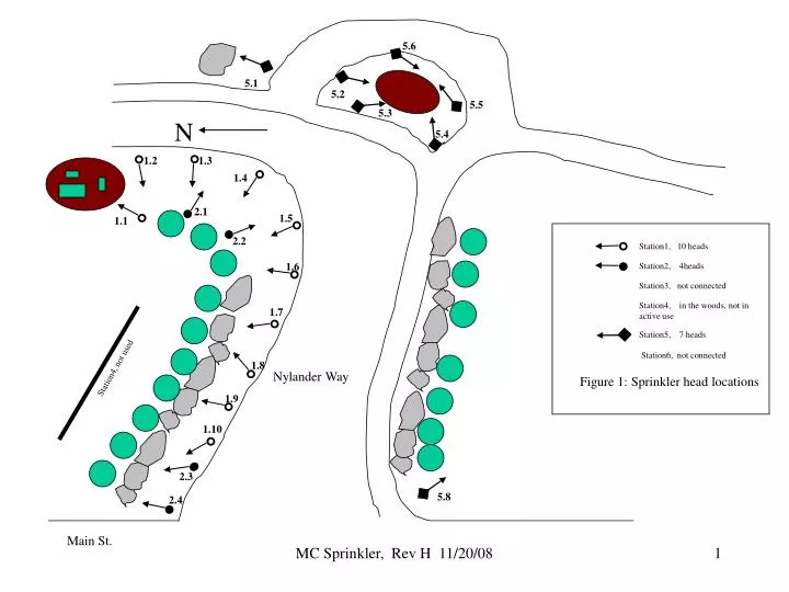
N 5.6 5.1 5.2 5.5 5.3 5.4 1.2 1.3 1.4 2.1 1.5 1.1 2.2 Station1, 10 heads 1.6 Station2, 4heads Station3, not connected Station4, in the woods, not in active use 1.7 Station5, 7 heads Station6, not connected Station4, not used 1.8 Nylander Way Figure 1: Sprinkler head locations 1.9 1.10 2.3 5.8 2.4 Main St. MC Sprinkler, Rev H 11/20/08
shed N well Valve Block 2. This is a schematic view, See Fig 3 for better view of physical location Cable 2 Grn wire Cable 1 Blowout connection Station1, 10 heads, 2 valves Not sure of exact layout of the two sections ylw wire Org wire Station2, 4heads, 1valve Red wire Station3, not connected Station4, in the woods, not in active use Valve Block 1 Nylander Way Station5, 7 heads, 2 valves Station4, not used Station6, not connected Figure 2: Schematic view with approximate location of pipes and valves Main St. MC Sprinkler, Rev H 11/20/08
N Valve Block 2 Valve Block 1 Figure 3: Location of Valves Nylander Way Main St. MC Sprinkler, Rev H 11/20/08
Revision History Rev D --5/5/04 Computerize earlier paper sketches kpd Rev E 5/6/04 Change valve block to show only 5 valves, not 6. Even though programmer has 6 stations, Mill Corner system only has 5 valves. There are 6 covers in the ground behind the utiliy boxes but one is a cover for the blowout connection (not a control valve) Revision History and NOTES pages added. Kpd Rev F 8/5/04 Tim Rodabaugh and Greg from Valley Green visited Mill Corner and reviewed the system with Kevin Dalton. Fig2 has been updated to show the location of the water lines. Two lines cross Nylander near the big rock then circle around the outer perimeter of the school bus turnaround. This differs from the layout shown in Rev E, which was a guess and was wrong. Tim indicated that more sprinkler heads could be added, ie, the system has expansion capability. Notes on page 4 were modified. Tim indicated that the control of the RED circuit may not be a simple as is indicated in Fig2. There maybe be second valve that is activated when the control box programs STATION 1 ON. The existence of this valve is only postulated and its location is unknown. It might also involve valve 3 or 4. More investigation could be done here. For now, the RED circuit is shown in FIG2 as 2 branches in parallel both controlled by a single valve, # 1. kpd MC Sprinkler, Rev H 11/20/08
Revision History Rev G - 5/31/06. Greg from Valley Green visited on Friday 5/26/06 to repair station 5 which was inoperative after recent sewer repair work near the turnaround. During this visit the existence of additional valves was confirmed. These valves were buried with no access covers. Greg added access covers. There was a vague valve reference in the 8/5/04 Rev F history note. These 2 newly discovered valves are near the control shed. One had been wired to station1 and its output connected to the flagpole spray head , aka 1.11 in Rev F. The other was/is wired to station5 and controls all the spray heads encircling the schoolbus turnaround. Greg has altered the connections. Greg connected these two valves in parallel to station 5, so that the spray head at the flagpole (formerly 1.11) is now 5.8. But the water line for 5.1 thru 5.7 is separate and unique from the line supplying 5.8 . See fig 2. I am now calling this group of valves near the control shed, Valve Block 2. The group of valves on the west side of Nylander Way I am calling Valve Block 1. Although there are 5 valves (plus1 blowout connection) in Block 1, there are only 3 stations or control signals. Station 1 is connected to 2 valves in Valve Block 1 via the yellow wire of Cable 1. Station 2 is connected to one valve via the orange wire of Cable 1. Station 4 is connected to two valves via the red wire of Cable 1. There are two multi-conductor cables leaving the control shed. Cable 1 has 3 active connections (ylw, org, red, see above) and travels from the shed, toward the Big Rock, under Nylander Way, to Valve Block 1. Cable 2 has 1 active connection (green)and travels from the control shed south about 30 feet to Valve Block 2. Reference to Station 3 has been eliminated in this document. There are no valves which are wired to Station 3. Greg also fixed a leak in the blowout connector that may have been caused or exacerbated by the failure of station 5 valve to open (due to sewer work, see above.) kpd Rev H 11/20/08 In the Spring of 2008, repairs were made along the inner circle of the turnaround. At that time, spray head 5.7 was removed and the line capped in that location. This was done since 5.7 was buried under the pine trees and ineffective. Diagrams have been changed to delete 5.7 kpd MC Sprinkler, Rev H 11/20/08
NOTES Since Summer of 2002, the system has been serviced by VALLEYGREEN LANDSCAPE PO BOX 489 CHELMSFORD, MA 01824 Karen -- Office Person Greg Knight -- Irrigation Tech 978 692-1013 valgrn2@aol.com Some portions of the existing system were installed by Kevin Sweeney (developer). The system was repaired and upgraded in 2002 . Head 5.8 was added in 2003. The system was used very little between 1995 and 2002. Programming manual is available in the tractor shed and in the Mill Corner BOG files. The sprinkler control shed is locked to avoid vandelism . The combination is 21-31-25. Kevin Dalton is available for consultation on the system. MC Sprinkler, Rev H 11/20/08