Download
1 / 20
200 likes | 352 Views
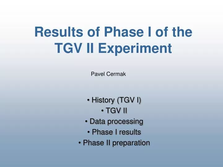
Results of Phase I of the TGV II Experiment. Pavel Cermak. History (TGV I) TGV II Data processing Phase I results Phase II preparation. Histor y (TGV I). (1994 – 2000) designed to study double beta decay of 48 Ca te lescope composed of 16 HPGe planar det ectors

E N D
Results of Phase I of the TGV II Experiment Pavel Cermak History (TGV I) TGV II Data processing Phase I results Phase II preparation
History (TGV I) • (1994 – 2000) • designed to study double beta decay of48Ca • telescope composed of 16 HPGe planar detectors • samples: foils of enriched 48Ca (80%), total mass 1.08g • shielding: 20cm of electrolytic copper, airtight box, BPE opencryostat • after 8700 hours: cryostat, PAs Pavel Cermak
History (TGV I) • TGV II • Data processing • Phase I results • Phase II preparation Pavel Cermak
TGV II • (2000 – ...) • to investigate bb processes in 106Cd (to focus on 2nEC/EC channel) • observables: 2 characteristic X-rays from de-excitation of 106Pd shell 2nEC/EC: Pavel Cermak
TGV II (predictions, measurements) T1/2 = 1.0·1020y(Suhonen) 8.7·1020y(Hirsch) 4.4·1021y(Simkovic) • Theoretical predictions: • Experimental results: (mostly to excited states of106Pd) T1/2>6.2·1018 y (Barabash, HPGe detector + Cd foil, Modane) T1/2>7.3·1019 y (Belli, NaI(Tl), geometrysimilar to TGV, Gran Sasso) T1/2(g.s → g.s.) >5.8·1017 y (Georgadze, measurement with116CdWO4 scintilators,Solotvina) Pavel Cermak
TGV II Location: Modane Underground Laboratory (4800 m.w.e.) Copper > 20 cm Airtight box Lead >10cm Boron filled polyethylene 16cm Pavel Cermak
TGV II (cryostat) HPGe Cd HPGe • 32 HPGe planar detectors ø60 mm x 6 mm (active area 2040mm2) • Total mass of samples: 10 - 25 g • E-threshold: ≈ 10 keV • Samples: 12x106Cd foils (~10g) Pavel Cermak
History (TGV I) • TGV II • Data processing • Phase I results • Phase II preparation Pavel Cermak
Background suppression (1) • besides the passive shielding, additional techniques for background suppression are used: Data after 8491 hours: • No selection • (1540663 ev.) • Odd-even coinc. • (287778 ev.) • E-window 19-22 keV • (4740 ev.) Pavel Cermak
Backgroundsuppression (2) • microphonic effect suppression • double shaping technique → scatter plot called ‘matrix’ • graphical cut application Matrix + effect of microphonic noise cut Pavel Cermak
History (TGV I) • TGV II • Data processing • Phase I results • Phase II preparation Pavel Cermak
Phase I result • acquisition with 10g of106Cd after 8491 hours: • data • linear background • Cd X-ray multiplet • excluded Pd X-ray • events Pavel Cermak
History (TGV I) • TGV II • Data processing • Phase I results • Phase II preparation Pavel Cermak
238keV area distribution along the cryostat: Phase II preparation (1) Pavel Cermak
Phase II preparation (2) Background source localization and elimination: Step 1: internal shielding bricks swapped → negative Step 2: detectors with holders swapped → negative Pavel Cermak
Phase II preparation (3) Step 3: endcap central part removal →positive weld Pavel Cermak
Phase II preparation (4) • test measurement with modified endcap – 1 month acquisition: Spectrum before and after endcap modification 238keV area reduction: • whole cryostat: 5x • four central detector pairs: 13x Pavel Cermak
Conclusions, near-term plans • Main run (1 year duration) with enriched 106Cd completed in 2006 • Phase I terminated giving new estimation on T1/2 (2nEC/EC, g.s.→g.s.) of 106Cd T1/2 = 1.0 · 1020y(Suhonen) T1/2 > 2.0 · 1020y(TGV II) T1/2 = 8.7 · 1020y(Hirsch) T1/2 = 4.4 · 1021y(Simkovic) • Main source of background inside the cryostat localized and removed • Phase II is starting: • more enriched material available (15g) • to continue for at least 3 years • factor 10 of improvement is reasonable Pavel Cermak
Future plans (1) 1. Physics Conceptual design study (MC, theoretical calculations, background study) – a) the possibility to measure 2nEC/EC decay with other isotopes (162Er, 156Dy) V.Ceron, J.Hirsch, arXiv:nucl-th/9911021v1 b) the study of the posibility to measure 0nEC/EC decay (152Gd g.s., 112Snexc. state– resonance enhancement of the 0nEC/EC process if Q – Qr < 1 keV) J.Bernabeu, A. deRujula, C.Jarlskog, Nucl. Phys. B223, 15 (1983) Z.Sujkowski, S.Wycech, Phys. Rev. C70, 052501, 2004 signature – X-rays < 100 keV + g or e-e+ or Majoron advantage: good value of the rates between 0nEC/EC and 2nEC/EC processes Pavel Cermak
Future plans (2) 2. Instrumentation • Planar pixellated detector (Si, GaAs, CdTe, thickness: 300/700/1000mm, Ge ~500mm) • Bump-bonded to Medipix readout chip containing amplifier, double discriminator, and counter in each pixel cell Medipix2 and TimePix Pixels: 256 x 256 Pixel size: 55 x 55 mm2 Area: 1.5 x 1.5 cm2 Medipix2 Quad Pixels: 512 x 512 Pixel size: 55 x 55 mm2 Area: 3 x 3 cm2 How about to use a pixellated detector for EC/EC measurements? (coincidences, position, X-ray energy) Pavel Cermak