Download
1 / 11
110 likes | 193 Views
Results from RF cogging sessions on Nov 20 to 23. A. Di Mauro, M. Krivda. Some basic numbers. Master RF = 400.788766 MHz 1 bucket = 2.4950799 ns 1 bunch = 10 buckets 1 ORBIT = 35640 buckets Revolution period 88.92464815 m s BPTX-A – IP2 = 145996.5 mm BPTX-C – IP2 = 145286.5 mm

E N D
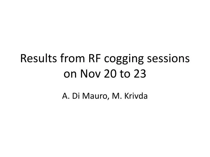
Results from RF cogging sessions on Nov 20 to 23 A. Di Mauro, M. Krivda
Some basic numbers Master RF = 400.788766 MHz 1 bucket = 2.4950799 ns 1 bunch = 10 buckets 1 ORBIT = 35640 buckets Revolution period 88.92464815 ms BPTX-A – IP2 = 145996.5 mm BPTX-C – IP2 = 145286.5 mm (DTOF = 2.37 ns) BPTX-A cable delay = 800.4 ± 0.1 ns (i.e. 196.76 ± 0.03 m with Vp=0.82*c) BPTX-C cable delay = 670.8 ± 0.1 ns (i.e. 164.89 ± 0.03 m with Vp=0.82*c) BPTX-C (on beam-2) BPTX-A (on beam-1) FOR BUNCHES CROSSING IN IP2 BPTX-C ARRIVES 127.23 ns BEFORE BPTX-A
Cogging with BPTX • Bucket 1 is defined as the 1st after the 3 ms empty abort gap (from 34442 to 35640) • Bunches in bucket 1 of the two beams collide in IP1 and IP5 • By delaying the beam 2 injection bucket by ¼ turn the IP is displaced by 1 octant (e.g., beam-1 bucket 1 collides with beam-2 bucket 8911 in IP2) • Cogging strategy: fix beam-1, adjust position of beam-2 bucket 1 so that buckets 1 collide in IP1/5 -> DT = 0 in IP1/5, DT= 66.693453 us in IP2
Cogging with BPTX • Two scopes installed close to rack C20 (where BPTX signals are fed to BPIM – Beam Phase and Intensity Monitor – boards), in front of CTP rack ORB1 BC1 ORB2 BC2 ORB from TTC MAIN ORB from TTC MAIN BC from TTC MAIN BPTX-A BPTX-C
First measurement with single beam BPTX1-ORB1 = 7.89646 us BPTX2-ORB2 = 42.17682 us ORB2-ORB1 = 2.573 us DT = (BPTX2-ORB2) + (ORB2-ORB1) – (BPTX1-ORB1) DT - 66.93453 = -29.840092 us -> IP rotated anticlockwise by ~ 1/6 orbit wrt IP1/5
Second try with single beam Beam-2 rotated clockwise by 29.84115 us BPTX1-ORB1 = 7.89646 us BPTX2-ORB1 = 74.5914128 us DT - 66.93453 = 0.0015 us
…and finally with both beams Beam-1 bucket 1 Beam-1 bucket 1
…and finally with both beams Fine tuning for ATLAS/CMS, ~ 1 ns correction
…and finally with both beams Fine tuning for ATLAS/CMS, 1 ns correction
..and in ALICE Beam-1 bucket 1 Without cable/TOF delay correction Beam-2 bucket 8911
..and in ALICE Beam-1 bucket 1 Beam-2 bucket 8911 With 127.23 ns cable/TOF delay correction <- Measured also by CMS