Download
1 / 50
500 likes | 699 Views
Real Mode and Protect Mode Architecture. Wannachai Wannasawade. Real Mode Memory Addressing. First 1 M byte of memory is called real memory or conventional memory 8088/86 to 80188/186 operate exclusively in real mode (upward compatible upto P4)

E N D
Real Mode and Protect Mode Architecture Wannachai Wannasawade Real Mode and Protect Mode
Real Mode Memory Addressing • First 1 M byte of memory is called real memoryor conventional memory • 8088/86 to 80188/186 operate exclusively inreal mode (upward compatible upto P4) • 80286+ can operate in both real & protectedmode • Default microprocessor mode for all intel family is real mode Real Mode and Protect Mode
Segment and Offset • All real mode memory addresses comprise of asegment address + offset address • Segment Address: located in segmentregisters, defines the beginning address ofany64K-byte memory segment • Offset Address: selects any location withinthe64K-byte memory segment (also calleddisplacement) • Note: All segments in real mode have a fixedlength of 64K-bytes Real Mode and Protect Mode
Real Mode Memory Addressing FFFFF 1FFFF Offset = F000 1F000 Segment register 64K-byte Segment 1 0 0 0 10000 00000 Real Mode and Protect Mode
Real Mode Memory Addressing Physical Address Segment + Offset by shift left segment 1 byte Example Segment is 2000H Offset is 1234H thus Physical Address is 20000+1234H = 21234H In real mode, Segment size are 64Kbyte per Segment Real Mode and Protect Mode
Real Mode Memory Addressing Default Segment and Offset Register It’s combination between segment and offset. For example CS:IP or CS:EIP Segment Offset Purpose CS IP Instruction Address SS SP or BP Stack Address DS BX,DI,SI,and Data Address 8,16 bit number ES DI for string String Destination instruction Address Real Mode and Protect Mode
Real Mode Memory Addressing Segment Offset Purpose CS EIP Instruction Address SS ESP or EBP Stack Address DS EAX.EBX,ECX, EDX, EDI,ESI, Data Address and 8,32 bit number ES EDI for string String Destination instruction Address FS No default General Address GS No default General Address Real Mode and Protect Mode
Default Segment & Offset Registers • A new program isloaded in the TPA atthe first free locationwhich is pointed at bythe free-pointer • Program loading ishandled automaticallyby the program-loader • Both of the abovepointers are managedby operating system Real Mode and Protect Mode
Advantages of segment:offset structure • Efficient memoryallocation • Suppose an applicationrequires 1000H bytes ofmemory for code, 190Hbytes for data and 200Hfor stack and no extrasegment Real Mode and Protect Mode
Default Segment & Offset Registers • Relocation: (i.e., usable without any change if moved in memory) • The scheme although complicated in perception, isuseful as it allows seamless relocation of programs • This allows the same program to be executed onslightly different machines (or slightly differentoperating systems) • This also allows real mode programs to work inprotected mode Real Mode and Protect Mode
Protected Mode Memory Addressing • Keyword: • More than 1Mbyte • Selector • Descriptor • Global Descriptor • Local Descriptor • System Descriptor • Application Descriptor Real Mode and Protect Mode
How do a Process/program Excecute? • What comprises the state of a running program (a process or task)? • If a second process, P2, is to be created and run (not shown), then the state ofP1 must be saved so it can be later resumed with no side-effects. • Since only one copy of the registers exist, they must be saved in memory. • We’ll see there is hardware support for doing this on the Pentium later. Real Mode and Protect Mode
Memory Resource Hierarchy • For now, let’s focus on the organization and management of memory. • Ideally, programmers would like a fast, infinitely large nonvolatile memory. • In reality, computers have a memory hierarchy: • Cache (SRAMS): Small (KBytes), expensive, volatile and very fast (< 5ns). • Main Memory (DRAM): Larger (MBytes), medium-priced, volatile and mediumspeed(<80ns). • Disk: GBytes, low-priced, non-volatile and slow (ms). • Therefore, the OS is charged with managing these limited resources andcreating the illusion of a fast, infinitely large main memory. • The Memory Manager portion of the OS: • Tracks memory usage. • Allocates/Deallocates memory. • Implements virtual memory. Real Mode and Protect Mode
Basic Memory Management • In a multiprogramming environment, a simple memory managementscheme is to divide up memory into n (possibly unequal) fixed-sizedpartitions. • These partitions are defined at system start-up and can be used tostore all the segments of the process (e.g., code, data and stack). • Advantage: it’s simple to implement. • However, it utilizes memory poorly. Also, in time sharing systems,queueing up jobs in this manner leads to unacceptable response timefor user processes. Real Mode and Protect Mode
Variable Sized Partitions In a variable-sized partition scheme, thenumber, location and size ofmemory partitions vary dynamically: (1) Initially, process A is in memory. (2) Then B and C are created. (3) A terminates. (4) D is created, B terminates. Real Mode and Protect Mode
Variable Sized Partitions • Problem: Dynamic partition size improves memory utilization butcomplicates allocation and deallocation by creating holes (externalfragmentation). • This may prevent a process from running that could otherwise run if theholes were merged, e.g., combining X1 and X2 in previous slide. • Memory compaction is a solution but is rarely used because of the CPUtime involved. • Also, the size of a process’s data segments can change dynamically,e.g. malloc(). • If a process does not have room to grow, it needs to be moved or killed. Real Mode and Protect Mode
Implementing Memory on Harddisk • The hard disk can be used to allow more processes to runthan would normally fit in main memory. • For example, when a process blocks I/O (e.g. keyboard input), itcan be swapped out to disk, allowing other processes to run. • The movement of whole processes to and from disk is calledswapping. • The disk can be used to implement a second scheme,virtual memory. • Virtual memory allows processes to run even when their total size(code, data and stack) exceeds the amount of physical memory(installed DRAM). • This is very common, for example, in microprocessors with 32-bitaddress spaces. • If an OS supports virtual memory, it allows for the execution ofprocesses that are only partially present in main memory. • OS keeps the parts of the process that are currently in use in mainmemory and the rest of the process on disk. Real Mode and Protect Mode
Virtual Memory • When a new portion of the process is needed, the OS swaps out older notrecently usedmemory to disk. • Virtual memory also works in a multiprogrammed system. • Main memory stores bits and pieces of many processes. • A process blocks whenever it requires a portion of itself that is on disk, much inthe same way it blocks to do I/O. • The OS schedules another process to run until the referenced portion is fetchedfrom disk. • But swapping out portions of memory that vary in size is not efficient. • External fragmentation is still a problem (it reduces memory utilization). • Two concepts: • Segmentation:Allows the OS to “share” code and enforce meaningfulconstraints on the memory used by a process, e.g. no execution of data. • Paging:Allows the OS to efficiently manage physical memory, and makes iteasier to implement virtual memory. Real Mode and Protect Mode
Paging and Virtual Memory • So how does paging work? • We will refer to addresses which appear on the address bus of mainmemory as a physical addresses. • Processes generate virtual addresses, e.g., MOV EAX, [EBX] • Note, the value given in [EBX] can reference memory locations that exceedthe size of physical memory. • (We can also start with linear addresses, which are virtual addressestranslated through the segmentation system, to be discussed). • All virtual (or linear) addresses are sent to the Memory ManagementUnit (MMU) for translation to a physical address. Real Mode and Protect Mode
Paging and Virtual Memory • The virtual (and physical) address space is divided into pages. • Page size is architecture dependent but usually range between 512- 64K. • Corresponding units in physical memory are called page frames. • Pages and page frames are usually the same size. • Assume: • •Page size is 4K • •Virtual Memory is 64K • •Physical memory is 32K. • • Therefore, there are • •16 virtual pages. • •8 page frames. • • Assume the process issues thevirtual address 0 -> Pagingtranslates it to physical address8192 (using the layout on right.) • • Similarly, 20500 is translated tophysical address 12K + 20 = 12308. • Note that 8 virtual pages are not mapped into physical memory(indicatedby an X on the previous slide). Real Mode and Protect Mode
Paging and Virtual Memory • A present /absent bit in the hardware indicates which virtual pagesare mapped into physical RAM and which ones are not (out on disk). • What happens when a process issues an address to an unmappedpage? • MMU notes page is unmapped using present/absent bit. • MMU causes CPU to trapto OS - page fault. • OS selects a page frame to replace and saves its current contents todisk. • OS fetches the page referenced and places it into the freed page frame. • OS changes the mem map and restarts the instruction that caused thetrap. • Paging allows the physical address space of a process to benoncontiguous ! • This solves the external fragmentation problem (since any set of pagescan be chosen as the address space of the process). • However, it generally doesn’t allow 100% mem utilization, since the lastpage of a process may not be entirely used (internal fragmentation). Real Mode and Protect Mode
Paging and Virtual Memory • Address translation by MMU Real Mode and Protect Mode
Paging and Virtual Memory Two important issues w.r.t the Page Table: • Size: • The Pentium uses 32-bit virtual addresses. • With a 4K page size, a 32-bit address space has 232/212 = 20or 1,048,576 virtual page numbers ! • If each page table entry occupies 4 bytes, that’s 4MB ofmemory, just to store the page table. • For 64-bit machines, there are 252 virtual page numbers !!! • Performance: • The mapping from virtual-to-physical addresses must be donefor EVERY memory reference. • Every instruction fetch requires a memory reference. • Many instructions have a memory operand. • Therefore, the mapping must be extremely fast, a couplenanoseconds, otherwise it becomes the bottleneck. Real Mode and Protect Mode
Page Table Design Alternatives • Single page table stored in an array of fast hardware registers. • OS loads registers from memory when a process is started. • Advantage: No memory references are needed for the page table. • Disadvantage: Context switches require the entire page table to beloaded. • If it is large, this will be expensive. • Page table kept entirely in main memory. • Single register points to the start of the page table. • Advantage: Context switches only require updating the registerpointer. • Disadvantage: One or more memory references are needed to readpage table entries for each instruction. • Modern computers keep “frequently used” page table entries on chipin a cache (similar to first alternative above) and the others in mainmemory (similar to the second alternative). Real Mode and Protect Mode
Multi-level Page Tables • Instead of using only one level of indirection, use two. Real Mode and Protect Mode
Multi-level Page Tables • This addresses page table size problem since many of the second-level page tablesneed not be defined (and therefore stored in main memory). • Note that two page faults can occur for a single memory reference. • If the second-level page table is not in memory, a page fault occurs. • If the page that the second-level entry refers to is not in memory, another page fault occurs. • In general, Page Framesare machine dependent with the following info: • Page Frame address: Most significant bits of physical memory address. • Present/Absent bit: If 1, page is in memory, if 0, it is on disk. • Modified bit: If set, page has been written to, e.g. it is ‘dirty’. • Referenced bit: Used in the OS page replacement algorithm. • Protection bits: Specifi es if data in page can beread/written/executed. Real Mode and Protect Mode
Translation Lookaside Buffers (TLBs) • With two-level paging, one memory reference could require three memoryaccesses ! • In order to reduce the number of times this occurs, a fast lookup table calleda TLB is added as a hardware cache in the microprocessor. Real Mode and Protect Mode
Translation Lookaside Buffers (TLBs) • Number of TLB entries varies from 8 to 2048. • Typically around 64. • When a TLB miss occurs: • A trap occurs and an OS routine handles the fault. The instruction isthen restarted. • The OS routine copies one (or more) page frame(s) from the pagetable in memory to one (or more) of the TLB entries. • Therefore, if page is referenced again soon, a TLB hit occurseliminating the memory reference for the page frame. Real Mode and Protect Mode
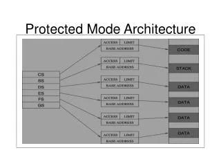
Protected Mode Memory Addressing • Allows access to data and programs located both above and within the first 1M byte of memory • While offset addresses (upto 32 bits or 4G bytes)are still valid, the segment addressing scheme isnot valid. • The segment register in this case contains a selector which selects a descriptor from adescriptor table • Real mode programs work in protected mode,because the difference is primarily in theinterpretation of different registers Real Mode and Protect Mode
Selectors & Descriptors • The selector in a segment register, selects oneof the 8192 descriptors stored in one of twodescriptors • Descriptor: describes the location, length andaccess rights of the memory segment • Types of descriptor tables • Global descriptor table (common to all programs) • Local descriptor table (application specific) • Each descriptor contains 8192 descriptors Real Mode and Protect Mode
Selectors & Descriptors • Base Address: indicates the starting location ofthe segment • For 80286, 24 bit (16 M bytes) • For 80386+, 32 bit (4 G bytes) Real Mode and Protect Mode
Selectors & Descriptors • Segment Limit: contains the last offset address foundin the segment • Example: if a segment begins at 60 0000H and ends at • 6000FFH, then • Base Address = 60 0000H • Segment Limit = 00FFH • For 80286, limit is 16 bits (upto 64K) • For 80386+, limit is 20 bits (upto 1 M, in standard mode) Real Mode and Protect Mode
Selectors & Descriptors Other New Features (in x386+ descriptor) Granularity bit (G): If G=0, the limit is in the range 0 – FFFFFH If G=1, the limit is multiplied by 4K, allowing a segment length of 4G bytes in steps of 4K bytes Example 1: Base = start = 1000 0000H; Limit = 001FFH; G = 0 End = Base + Limit = 10000000H + 001FFH = 1000 01FFH Example 2: Base = start = 1000 0000H; Limit = 001F FXXXH; G = 1 End = Base + Limit = 10000000H + 001F FXXXH = 101F FFFFH Real Mode and Protect Mode
Selectors & Descriptors Other New Features AV bit: AV bit is used to indicate whether the segment isavailable or reserved by OS or another application D bit: Indicates how x386+ access register and memorydata in the protected mode D = 0 16-bit instruction mode D = 1 32-bit instruction mode This bit value can be over-riden Real Mode and Protect Mode
Access Rights Byte Real Mode and Protect Mode
Segment Registers in Protected Mode Privilege levels are used in multiuser environments (highest RPL = 00) Real Mode and Protect Mode
Selection of a Descriptor DS=0008H Descriptor 1, PL = 00 from Global Descriptor Descriptor Contains Base Address: 0010 0000H Segment Limit = 000FF H Note: Descriptor 0 is not for programming access Real Mode and Protect Mode
Program Invisible Registers • Used to access and specify the addresses ofglobal & local descriptor tables • Not addressable for programming • Accessible to OS • Each segment register has a program invisibleportion (which acts like an address cache) tostore the corresponding descriptor informationfor a segment register Real Mode and Protect Mode
Program Invisible Registers Real Mode and Protect Mode
Memory Paging • The memory paging mechanism allows for anyphysical address to be assigned to any linear address(i.e., relocation is possible) • Linear address is an address generated by a program. • Memory paging allows for a linear address to beinvisible translated to a physical address • The scheme allows usage of extended memoryresources such as memory between video & systemBIOS etc. • Paging mechanism can be used in both real andprotected modes Real Mode and Protect Mode
Paging Registers Paging unit is controlled by µP’s control registers (CR0-CR3 inx386+ and CR4 in Pentiums) Real Mode and Protect Mode
Paging Registers • Some of the important parts of the paging mechanism are inCR0 and CR3, e.g., • PG: (in CR0) PG=1 enables paging mechanism, else linearaddress is directly converted to a physical address • PCD: (in CR3) controls the PCD pin of µP, i.e., PCD pin equals logic 1 during bus cycles that are not pages (for controlling L2 cache) • PWT: (in CR3) controls the PWT pin of µP, i.e., PWT pin equals logic 1 during bus cycles that are not pages (for controlling write through cache) • Page directory base address: (in CR3) locates the page directory for page translation unit at any 4K byte boundary inthe memory system Real Mode and Protect Mode
Paging Registers • The page directory has 1024 directory entries oflength 4 bytes each • Each page directory entryaddresses a pagetable that contains 1024 entries Real Mode and Protect Mode
Other invisible registers • GDTR (global descriptor table register) • IDTR (interrupt descriptor table register) • LDTR (local descriptor table register): A • selector into GDTR, which is allocated as localdescriptor table • TR (task register): hold a selector that defines atask (an application program or subprogram) • Note task switching can done at a rate of 17µs Real Mode and Protect Mode
Linear Address Format • Page directory entry: leftmost 10 bits (4 M bytes insize), e.g., linear addresses0000 0000H to 003F FFFFH address 1st page (page 0) • Page table entry: contains the next 10 bits (4 K byterange) after the page directory entry, e.g., 0000 0000Hto 0000 0FFFH refer to both directory and table equal0 • Page offset address: selects a byte in the 4K bytememory page Real Mode and Protect Mode
Linear Address Format Example: If page table 0 entry contains address 00100000H Then For linear addresses 0000 0000H to 0000 0FFFH The corresponding physical address is 0010 0000H to 0010 0FFFH Real Mode and Protect Mode
TLB – (translation look-aside buffer) • TLB is a dedicated cache (queue) structure to holdthe 32 most recent page directory and table entries • Pentium+ processors have TLBs for each data andinstruction caches Real Mode and Protect Mode
Page Directory and Page Table Real Mode and Protect Mode
Page Directory and Page Table Relocated memory spaceRegular paged memory Real Mode and Protect Mode
Page Directory and Page Table • There is only 1 page directory in the system • The page directory has 1024 doublewordaddresses (of page tables) stored • Each page table is also 4K bytes in size andhas 1024 entries • If entire 4G bytes of RAM are paged, more than4M byte are required for the storage of pagingtables Real Mode and Protect Mode