Download
1 / 9
200 likes | 810 Views
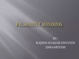
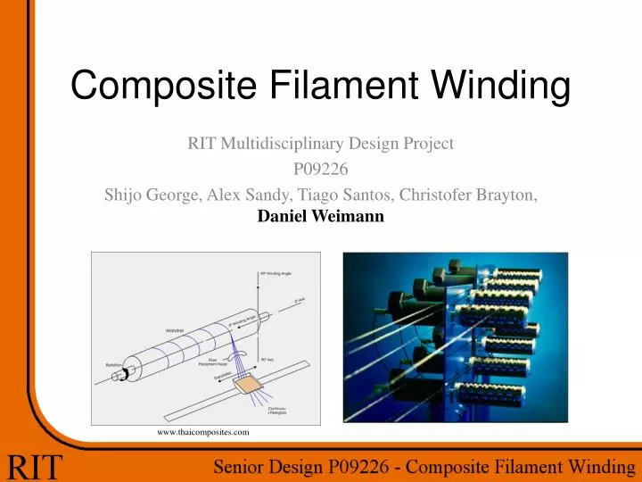
Composite Filament Winding. RIT Multidisciplinary Design Project P09226 Shijo George, Alex Sandy, Tiago Santos, Christofer Brayton , Daniel Weimann. www.thaicomposites.com. Project Background. Composite Tubing Carbon Fiber, Fiberglass, Kevlar Benefits High strength Light weight

E N D
Composite Filament Winding RIT Multidisciplinary Design Project P09226 Shijo George, Alex Sandy, Tiago Santos, ChristoferBrayton, Daniel Weimann www.thaicomposites.com
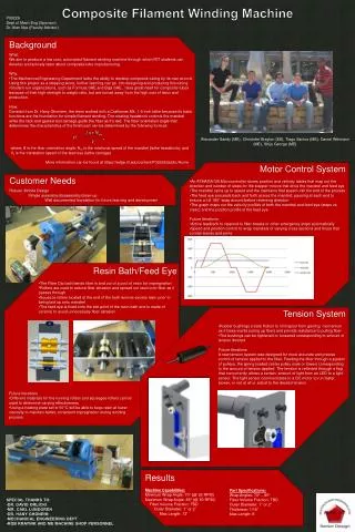
Project Background • Composite Tubing • Carbon Fiber, Fiberglass, Kevlar • Benefits • High strength • Light weight • High creep and fatigue performance • Chemical and corrosion resistance • Uses • Drive shaft/half shaft • Golf Clubs • Pipes • Pressure vessels
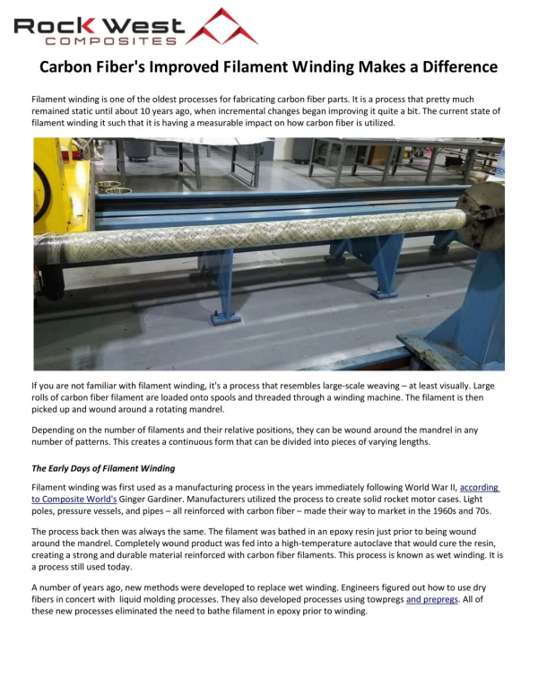
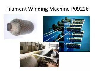
Filament Winding • Continuous strand of impregnated fibers wound onto a mandrel • Often computer controlled • Mandrel may be removed post cure
Project Goals • Capability • Develop filament winding within department • Base for future senior design teams • Composite tube • Variable length • Variable wrap angle • Machine • Robust expandable design • Simple partially automated operation • Test • Compare theoretical and experimental results • Risks • Budget • $2000 Preliminary budget • Design • Integration • Control structure • Resin Impregnation • Tension • Fiber Slip • Time • 2 quarters • 11 week build/test • Part lead time
Responsibilities • Feedeye • Lead screw calculations • Carriage, mounting • Tension • Explore capabilities • Electromagnetic Brake • Motor Brake • Work with Chris (EE) to ensure control • Mandrel • Lathe condition • Chuck, Tailstock • Solid Modeling
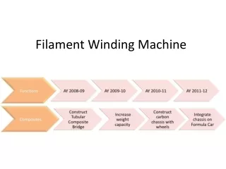
Project Plan • Detailed Design Review • Multiple reviews 2/9-2/18 • Executive Review • 2/20 • Finalized Parts List • 2/25 • Senior Design 2 • Build Stage • Working Machine 4/24 • Testing • 4/27 – 5/1
Desired Outcome • Develop capability within department • Create composite wound tube • Repeatable • Confirmable through testing • Base for further development • Senior Design • Increase Spools • Advanced controls • Multi-axis
Closing Questions ? Contact Information Daniel Weimann DSW1104@rit.edu 724-454-9622 32 Avondale Park Rochester NY 14620