Download
1 / 6
170 likes | 884 Views
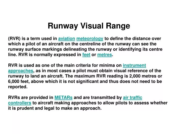
Runway Visual Range (RVR) is a term used in aviation meteorology to define the distance over which a pilot of an aircraft on the centreline of the runway can see the runway surface markings delineating the runway or identifying its centre line. RVR is normally expressed in feet or metres .

E N D
Runway Visual Range (RVR) is a term used in aviationmeteorology to define the distance over which a pilot of an aircraft on the centreline of the runway can see the runway surface markings delineating the runway or identifying its centre line. RVR is normally expressed in feet or metres. RVR is used as one of the main criteria for minima on instrument approaches, as in most cases a pilot must obtain visual reference of the runway to land an aircraft. The maximum RVR reading is 2,000 metres or 6,000 feet, above which it is not significant and thus does not need to be reported. RVRs are provided in METARs and are transmitted by air traffic controllers to aircraft making approaches to allow pilots to assess whether it is prudent and legal to make an approach.
RVR is also the main criteria used to determine the category of visual aids that are installed at an airport. The International Civil Aviation Organisation ICAO stipulates that for RVR values above 550 m, CAT I lighting shall be installed, if RVR is between 300 m and 549 m then CAT II lighting is required. CAT IIIa is installed for RVR values between 175 m and 300 m. CAT IIIb is required for RVR values between 50 m and 175 m while there is no RVR limitation for CAT IIIc visual aids.[citation needed] Originally RVR was measured by a person, either by viewing the runway lights from the top of a vehicle parked on the runway threshold, or by viewing special angled runway lights from a tower at one side of the runway. The number of lights visible could then be converted to a distance to give the RVR. This is known as the human observer method and can still be used as a fall-back.
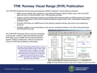
Today most airports use Instrumented Runway Visual Range or IRVR, which is measured by devices called (forward scatter meters) which provide simplified installation as they are integrated units and can be installed as single unit(s) at a critical location along the runway or transmissometers which are installed at one side of a runway relatively close to its edge. Normally three transmissometers are provided, one at each end of the runway and one at the mid-point. In the US, Forward Scatter RVRs are replacing transmissometers at most airports. According to the US Federal Aviation Administration: "There are approximately 279 RVR systems in the NAS, of which 242 are forward scatter NG RVR Systems and 34 are older Transmissometer Systems."
A transmissometer is an instrument for measuring the extinction coefficient of the atmosphere, and for the determination of visual range. It operates by sending a narrow, collimated beam of energy (usually a laser) through the propagation medium. A narrow field of view receiver at the designated measurement distance determines how much energy is arriving at the detector, and determines the path transmission and/or extinction coefficient. Atmospheric extenction is wavelength dependent phenomenon, but the most common wavelength in use for transmissometers is 550 nm, which is right in the middle of the visible waveband, and allows a good approximation of visual range. Transmissometers are sometimes referred to as telephotometers, transmittance meters, orhazemeters. The term transmissometer is also used by oceanographers and limnologists to refer to a device for measuring the optical properties of natural water. In this context, a transmissometer measures thetransmittance or attenuation of incident radiation from a light source with a select wavelength, often 660 nm, through a defined cell volume.
EMOR - Extended MOR Technology Latest generation transmissometer technology makes use of a co-located forward scatter visibility sensor on the transmitter unit to allow for higher accuracies over an Extended Meteorological Optical Range or EMOR. After 10,000 meters the accuracy of transmissometer technology drops off and it is at higher visibilities that forward scatter visibility sensor technology is more accurate. The co-location of the two sensors allows for the most accurate technology to be used when reporting on current visibility. The forward scatter sensor also enables auto-alignment and auto-calibration of the transmissometer device.
Unidades Una candela se define como la intensidad luminosa de una fuente de luz monocromatica de 540 THz que tiene una intesidad radiante de 1/683 vatios por estereorradián, o aproximadamente 1.464 mW/sr. La frecuencia de 540 THz corresponde a una longitud de onda de 555 nm, que se corresponde con la luz verde pálida cerca del límite de visión del ojo. Ya que hay aproximadamente 12.6 estereorradianes en una esfera, el flujo radiante total sería de aproximadamente 18.40 mW, si la fuente emitiese de forma uniforme en todas las direcciones. Una vela corriente produce con poca precisión una candela de intensidad luminosa.