Download
1 / 34
340 likes | 513 Views
iGen Fuser Bearing Project P11511. Agenda. Project Team, Faculty, and Customer. Project Team: Project Lead: Kevin Argabright (ME) Team Members: John Fitch Dean (ME) Mike Buonaccorso (ME) Justin Eichenberger (ME) Project Guide: William Nowak (Xerox Corporation) Faculty:

E N D
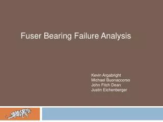
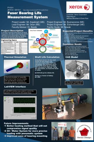
Project Team, Faculty, and Customer • Project Team: • Project Lead: Kevin Argabright (ME) • Team Members: John Fitch Dean (ME) Mike Buonaccorso (ME) Justin Eichenberger (ME) • Project Guide: William Nowak (Xerox Corporation) • Faculty: • Consultant Dr. Stephen Boedo • Customer: • Xerox Corporation Erwin Ruiz Melissa Monahan
Running Conditions of Fuser Xroller forces are 184lbs each Reaction force of 360lbs/bearing Fuser rotates at 79.8RPM Outer race of the fuser bearings experience a temperature of 230°F
Customer Needs • Develop method to characterize physical properties of bearings over their physical life • Collect data on bearing properties • Correlate physical property to end of life • Incorporate multiple sensors • Characterize physical properties over the bearing's physical life • Create failure criteria • Document the procedure (Testing) • Testing bearings is quick and easy to do • Document the procedure (Collecting Data)
Weighted Customer Needs • Used a pairwise comparison chart • Most Important Needs: • Develop method to characterize physical properties of bearings over their physical life • Document the procedure for collecting data
Project Scope • Create a measuring tool to aid Xerox Corporation’s engineering team in collecting necessary data for characterizing bearing life in the iGen Fuser Assembly
Concept Selection • Design chosen • Fixed Outer Race • Camshaft • DC motor • Conduction to outer surface • Belt • Accelerometer • Thermistor • Microcontroller • Labview
P11511 Senior Design Review Thank you for attending!
Loading the Bearing • Total load seen by the bearing = 360lbs • Pressure roll force: 600lb • Heat roll force: 184lb/roll • Angle between heat rolls: 60° • Using a pneumatic cylinder to apply load • Sized according to force needed (plus weight of object applying load) • Pressure regulator will be used to adjust air pressure applied to cylinder • Maximum pressure available = ~75psi
Pneumatic Cylinder • Parker “Pancake Style” pneumatic cylinder (3.0NLPR9X1.00) • Bore size: 3.00” • Stroke size: 1.00” • Rod thread size: 5/8-18 female • Length: 2.625” • Cost: $181.67 • Source: MSC Direct
Pressure Regulator • Jupiter Pneumatics Air pressure regulator with pressure gauge (4710302535JP) • Port Size: 1/4” • Maximum PSI: 120psi • Width: 1.97” • Height: 1.97” • Cost: $11.36 • Source: MSC Direct
Pushing Rod • 5/8”-18 Threaded Stud (91187A650) • Thread: 5/8”-18 • Material: 18-8 SS • Overall Length: 12” • Cost: $13.33 • Source: McMaster-Carr
Bearing “Pusher” and Sensor Holder • Made from (1) 6” x 6” x 1” Aluminum Plate (89155K971) • Material: Aluminum 6061 • Both pieces cut from 1 plate • 1/8” width x 1/16” depth keys on both sides for guide rails • Oversized hole for pushing rod on bottom
Guide Rails • Precision shaft with keyhole (7398K22) • Shaft diameter: 1/2” • Material: 304 SS • Overall Length: 12” • 1/8” width x 1/16” depth keyhole • Will need to tap hole into bottom for mounting • Cost: $44.32 ($22.16ea) • Source: McMaster-Carr
Mounting Plate • Made from (1) 8” x 8” x 1” Aluminum Plate (9246K61) • Material: Aluminum 6061 • Holes mount guide rails and pneumatic cylinder • Countersunk holes from the bottom allow mounting to another table • Mounting holes spaced at 3” and 6” distances for mounting to table with inch spacing mounting holes • Cost: $47.00 • Source: McMaster-Carr
Mica Band Heater Cost=~$200
Thermal Resistant Coating • Swain Tech Coatings Inc.963 North RoadScottsville, NY 14546 • Recommends Zirconia Coating • Excellent Thermal Insulation • Approx. $175 for both parts • 2-2 ½ week turn around time
Attaching heater to Sensor Holder/Pusher • JB Weld • Resistant up to 500 deg F • Bonds to virtually any material including aluminum, steel, and ceramic • McMaster-Carr Part #7605A11-$5.91