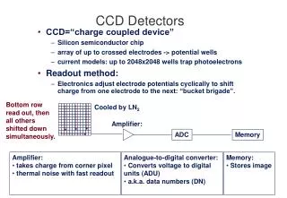
Download
1 / 34
340 likes | 549 Views
X-ray CCD Detectors for Astronomy and Space Science. Andrew Holland a.d.holland@open.ac.uk. Focussed X-ray Imaging. The ESA XMM/Newton Spacecraft. 3 co-aligned optics, each comprising 58 nested Ni shells. Focal plane detector arrays providing imaging and spectroscopy.

E N D
X-ray CCD Detectors for Astronomy and Space Science Andrew Holland a.d.holland@open.ac.uk
Focussed X-ray Imaging The ESA XMM/Newton Spacecraft 3 co-aligned optics, each comprising 58 nested Ni shells Focal plane detector arrays providing imaging and spectroscopy
XMM EPIC MOS Cameras • 2 UK MOS cameras, having focal plane arrays of 7 CCDs • Share their telescopes with the 2 RGS instruments • Broad-band from 0.3-10 keV, ~35 mm depletion • Increase in throughput, high energy QE and sub-keV resolution possible • Redundancy comes from multiple detectors (and cameras) 6 cm
Future X-ray Astronomy Missions • HXMT (China) ~2012 • China’s first X-ray astronomy mission • Collimated • NeXT (Japan) ~2013 • X-ray telescope • IXO (ESA/NASA/Jaxa) ~2018 • Merger of XEUS and Con-X
IXO baseline concept • “XEUS” becomes “IXO” • IXO science goals encompass all of XEUS and Con-X core science. • L2 halo orbit • Baseline is one spacecraft with an extensible optical bench instead of two spacecraft in formation-flying configuration • requires the provision of a focal plane instrument interchange mechanism • ESA Si-pore optics remain in the baseline for IXO, but US will study slumped-glass alternative in parallel • NB parallel ESA study of slumped glass was already anticipated for XEUS. Extendible Bench with light tight curtain (not shown) Focal Plane Spacecraft bus Mirror Silicon Glass
IXO baseline concept • Focal length is now 20-25m instead of 35m for XEUS • implications for the effective area as a function of energy and the instrument fields of view. • Key requirements: • affective area ~3 m2 @ 1.25 keV; ~1 m2 @ 6 keV • angular resolution 5 arcsec • Single optic with design optimized to minimize mass and maximize the collecting area ~3.4m diameter figure courtesy Günther Hasinger
IXO baseline concept • Baseline instruments are: • an X-ray wide field imaging spectrometer (=XEUS WFI) • a high spectral resolution non-dispersive X-ray spectrometer (=XEUS NFI, Con-X XCS) • an X-ray grating spectrometer (=Con-X XGS) • “allocation for further payload elements with modest resource demands” • Potential fields of view: • WFI: 12 arcmin • NFI: 5 arcmin figure courtesy Nick White
Key Reasons to Continue MOS Activity • Complementary technology to DEPFET • Reduces Technical Risk • Instrument Background • Instrument background IS lower in the XMM MOS CCDs • Redundancy • Key unknown risk of micrometeorite hit killing FPA • 2 separate WFI sub-systems virtually remove risk of catastrophic failure • Hope to re-introduce increased FOV for WFI
Key Developments Beyond XMM/EPIC • Key DEPFET Alternative Technology Required • Charge Transfer Speed increase • Key E-WFI Developments Required • Baffle and Straylight analysis • Common Development Requirements • High throughput using a low noise multi channel ASICs • Improved high energy QE • High Sensitivity (low background) • Improved spectroscopic resolution at low energies • Radiation hard
Aluminium tracks Increased Transfer Speed Polysilicon electrodes • A >30x increase in the throughput for the IXO optic can be achieved by • Fewer pixels (1/3) • An increase in readout speed (3x) • An increase in number of output nodes (8x) • For a 2x1” format detector, frame time is 30 ms • To retain >100:1 integration:transfer time – Frame transfer time should be <300 ms • Line transfer time <<0.5 ms • This requires the new technique of metal buttressing over the polysilicon electrodes to reduce resistance • This technique has been developed for the CPCCD for LHC at e2v
Low Background Detectors for E-WFI Out of field background (D.Lumb report) • Optimal sensitivity combines • Expected source spectrum • Mirror efficiency (basically <2 keV) • Detector QE • Detector background • XMM detectors sensitive to • Single or double sided detection (+100%) • Thickness of “Entrance window” (+50%) • Pixel size (~10-20%) • We are performing a study to maximise instrument sensitivity • Warning against using many elements in the baffle/camera
Energy Geant4 Model and Results
Instrument Background Study • Extensive study performed using Geant-4 comparing to EPIC MOS+pn, Suzaku and Swift instruments • For XMM EPIC the dominant background is LE electrons from the camera • EPIC array averaged area to primary protons ~14 cm2, ~50/s, >99.9% penetrating particles rejected • Residual background from soft electrons from surroundings plus Compton electrons internal to sensor • With scintillator veto shield, averaged area >300 cm2, ~ 1200/s, would add to dead time, high-Z would also create more gamma background • FI MOS CCDs inherently lower sensitivity to these than fully depleted BI structures • Need to perform study into reducing the electron component off the shield • Further Geant-4 model development to be undertaken • Concerns over high-Z active shields impacting Si background + coatings • EPIC used Al shielding specifically to minimise background
High Speed Readout • High throughput required to minimise pile-up • System noise specification of 5 e- rms. • XMM/EPIC 1 node at 160 kHz • XEUS minimum requirement : 8 nodes at 1 MHz • 30 x faster than XMM/EPIC • Initial development with RAL (1 and 4 channel, 6-10 e- noise) • Aim to develop a full 8 channel design Clock timing diagram 2-channel CDS ASIC 4 Channel ASIC
Increased Detection Efficiency(see poster by Murray) • Use of high purity bulk (FZ) materialcan increase depletion depth • De-coupling rear substrate from thatlocal to FET can enable increased bias • 300 mm depletion for -100V on substrate • 2nd generation devices tested using512x2048 format – 13.5mm pixels • Used on-chip binning to explore FWHM resolution vs. pixel size ~93 µm depletion ~295 µm depletion ~35 µm depletion CCD247 Quantum Efficiency Measurements CCD247 Spectral Resolution Measurements (VSS = -100 V)
NFI A2597 E-WFI Increase in Science from the E-WFI • IXO optic has 3.5x the focal length of XMM • Useable field to 20 arcmin andlimited by detector size • Needs a very large focal plane array • Survey & find first black holerequires use of all of field • Proposing the DEPFET for the central field • MOS CCDs to enhance field coverage by 9x • Gives access to much more data
The XEUS E-WFI • An X-ray camera for XEUS : dual technology to cover the target and serendipetous science • Much larger array than XMM EPIC • High rate DEPFET central array, surrounded by a CCD outer ring • Only one possible CCD construction shown Module 18 cm CCD ASIC Al mount Si substrate TEC Be-plate Al fingers Flex
The Swept Charge Device • Non-imaging CCD-based sensor for XRF • Developed under the UK Impact programme ~1998 • New generation of devices designed in 2007
The New Family of SCDs • Non-imaging CCD technology for XRF • New design provides improvements to: • Radiation hardness • Readout speed • Operating temperature • 2 phase operation with 100 mm pitch “L”-shaped electrodes Dummy output node
CCD234 and CCD235 • CCD234 – Area = 100 mm2 • CCD235 – Area = 5 mm2 CCD235
Large Pixels (100 mm) • X-ray optic PSF is ~1mm in diameter • Fewer/larger pixels promote an increase in frame rate • New CCDs tested with 100 mm pixel pitch for HXMT • Large pixels demonstrating high charge collection and good CTE for X-ray spectroscopy • Improved radiation hardness due to charge confinement – needs verification by tests • CCD236 shown – 2 phase, 100 mm pitch Cu-K in CCD235
Leakage Current • Devices only designed for small signal handling, <10k e- • CCD236 leakage saturates device at room temperature • Leakage current measured at 100 kHz readout rate
CCD235 Resolution at Elevated Temperatures • Cu-K spectra in the CCD235 operated at 100 kHz above room temperature • Is this a record for resolution vs. temperature? • Note that the leakage contribution can be reduced by running faster • Elemental identification at +50oC is possible
SXI on HXMT • Working with IHEP in Beijing to use an array of CCD236 SCDs for to soft X-ray imager on HXMT • Detector area = 320 cm2 Soft X-ray Detector(SCD, 400 cm2)
Main Characteristics of HXMT Instruments • Main Detector NaI(Tl)/CsI(Na) Phoswich • Total Detect Area ~5000 cm2 • Energy Range 20~250 keV • Energy Resolution ~19% (@60keV) • Field of View 5.7°x 5.7°(FWHM) • Source Location ≤1 arcmin(20) • Angular Resolution ≤5 arcmin(20) • Secondary Instruments IEXD(7-30 keV, SiPIN, 1000 cm2), SXD ((1-15 keV, SCD, 400 cm2) • Mass ~2500 kg (payload ~1100 kg) • Dimension 2.0×2.0×2.8 m3 (L×W×H) • Nominal Mission lifetime 2-3 years • Orbit Altitude 550km,Inclination 43° • Attitude Three-axis stabilized
HXMT SCD Modules • Aim to construct a detector array behind an X-ray collimator system • Target of 320 cm2 detection area • Design concept includes 4 CCD236 devices on a ceramic module • Collecting area is built up using a mosaic of these modules
SCDs for Lunar Mappingtalk by D. Smith • SCDs used in the D-CIXS instrument on ESA’s Smart-1 lunar orbiter • Detectors heavily radiation damaged during the long transit to the moon • Also to be flown on the C1XS spectrometer on ISRO’s Chandrayaan-1 lunar orbiter • Improved instrument design to meet science goals over 2 year mission duration • Both instruments use an array of SCDs in a 4x1 array package • 6 such packages used per instrument, providing 24 sensors • D-CIXS package shown below with D-CIXS instrument (RAL) 4 SCDs driven in parallel requiring only 12 connections
Elemental Mapping of the Moon • C1XS will produce elemental maps like the one shown from the NASA Clementine mission:
Potassium Ka Calcium Ka Aluminium Ka Titanium Ka Vanadium Ka Silicon Ka Calcium Kb Magnesium Ka Manganese Ka Iron Ka Phosphorous Ka Sodium Ka Chlorine Ka Iron Kb Oxygen Ka Tail of noise peak, as a result of image processing Etna Basalt(Polished, 10 minute data collection)
Spin-Off into other areas • Utilising the photon-counting mode of CCDs • X-ray Fluorescence • Analysis of contaminants • X-ray diffraction • Portable in-situ XRF/XRD for geology • www.inXitu.com • Beta Autoradiography • Thin tissue imaging using 3H, 14C • www.xcam.co.uk
Conclusions • MOS CCDs are being developed for future X-ray instruments in space science • Over the next year the IXO baseline configuration is likely to change (watch this space…) • Development of critical technology components is being addressed • Readout ASICs • Transfer time • Increased QE • Large pixels • Currently no funding for a single demonstrator model incorporating all elements • Modelling of instrument background is identifying the key contributors to aid their reduction in XEUS • SCD technology is being applied to XRF for elemental mapping for Lunar science • Spin-off is occurring into terrestrial XRF, XRD and Beta Autoradiography