Download
1 / 19
220 likes | 361 Views
LEADER Project: Task 5.5. Analysis of Representative DEC Events of the ETDR with RELAP5. G. Bandini - ENEA/Bologna LEADER 5 th WP5 Meeting JRC-IET , Petten , 26 February 2013. Outline. Analysed DEC transients at EOC Transient r esults Conclusions. Analyzed DEC transients at EOC.

E N D
LEADER Project: Task 5.5 Analysis of Representative DEC Events of the ETDR with RELAP5 G. Bandini - ENEA/Bologna LEADER 5th WP5 Meeting JRC-IET, Petten, 26 February 2013
Outline • Analysed DEC transients at EOC • Transient results • Conclusions
Analyzed DEC transients at EOC Main events and reactor scram threshold UNPROTECTED PROTECTED
TR-4: Reactivity insertion (UTOP) (1/2) • ASSUMPTIONS: • Insertion of 250 pcm in 10 s without reactor scram • No feedwater control on secondary side • Fuel-clad linked effect fuel expansion according to clad temperature (closed gap) Total reactivity and feedbacks Core and MHX powers • The reactivity insertion is mainly counterbalanced by Doppler effect initial core power rise up to 680 MW 4
TR-4: Reactivity insertion (UTOP) (2/2) Core temperatures Core temperatures • MAIN RESULTS: • Maximum clad temperature remains below 650 °C • Maximum fuel temperature of 2930 °C at t = 57 s (hottest FA, middle core plane, fuel pellet centre) exceeds the MOX melting point (~2670 °C) only local fuel melting no extended core melting 5
T-DEC1: ULOF transient (1/2) • ASSUMPTIONS: • All primary pumps coastdownwithout reactor scram • No feedwater control on secondary side • Fuel-clad not-linked effect fuel expansion according to fuel temperature (open gap) Active core flowrate Core and MHX powers • Natural circulation in the primary circuit stabilizes at 23% of nominal value • Core power reduces down to about 200 MW due to negative reactivity feedbacks 6
T-DEC1: ULOF transient (2/2) Core temperatures Total reactivity and feedbacks Core temperatures • MAIN RESULTS: • Initial clad peak temperature of 764 °C • Max clad temperature stabilizes below 650 °C • No clad failure is expected in the short and long term • No vessel wall temperature increase 7
T-DEC3: ULOHS transient (1/2) • ASSUMPTIONS: • Loss of feedwater to all MHXs without reactor scram • Startup of DHR-1 (3 out of 4 IC loops ofin service) • No heat losses for the external vessel wall surface Core and MHX powers Core and vessel temperatures • Core power progressively reduces down towards decay level • Maximum clad and vessel temperatures rise up to 700 °C after about one hour 8
T-DEC3: ULOHS (2/2) Total reactivity and feedbacks Core temperatures • MAIN RESULTS: • No fuel rod clad rupture is expected in the medium term • No vessel failure is expected in the medium term (to be verified) • Enough grace time is left to the operator to take the opportune corrective actions and bring the plant in safe conditions in the medium and long term 9
T-DEC4: ULOHS+ULOF transient (1/2) • ASSUMPTIONS: • Loss of feedwater to all MHXs and all primary pumps without reactor scram • Startup of DHR-1 (3 out of 4 IC loops of in service) • No heat losses from the external vessel wall surface Active core flowrate Core and MHX powers • Natural circulation in primary circuit reduces down to very low value (around 1%) • Core power progressively reduces down towards decay level 10
T-DEC4: ULOHS+ULOF transient (2/2) Core temperatures Total reactivity and feedbacks • MAIN RESULTS: • Max T-clad rises up to 800 °C after about 15 minutes and stabilizes around 825 °C no fuel rod clad rupture is expected in the short and medium term (to be verified) • No vessel failure is expected in the medium and long term • Enough grace time is left to the operator to take the opportune corrective actions and bring the plant in safe conditions in the medium and long term 11
TO-3: FW temp. reduction (1/2) Active core flowrate (short term) • ASSUMPTIONS: • Loss of one preheater (FW temperature from 335 °C down to 300 °C in 1 s) + all primary pumps coastdown • Reactor scram at t = 2 s on low primary pump speed signal • Startup of DHR-1 (4 IC loops in service) Core temperatures Active core flowrate (long term) 12
TO-3: FW temp. reduction (2/2) Core decay and MHX powers Primary lead temperatures • MAIN RESULTS: • Power removal by 4 IC loops of DHR-1 system is about 7 MW • No risk of lead freezing after DHR-1 startup • Lead freezing at MHX outlet is reached after about 2 hours (cold lead at the MHX outlet flows to the core inlet without mixing with the hotter lead of the cold pool surrounding the MHXs) 13
TO-6: FW flowrate + 20% (1/2) Active core flowrate (short term) • ASSUMPTIONS: • FW flowrate increase of 20% + all primary pumps coastdown • Reactor scram at t = 2 s on low primary pump speed signal • Startup of DHR-1 (4 IC loops in service) Core temperatures Active core flowrate (long term) 14
TO-6: FW flowrate + 20% (2/2) Core decay and MHX powers Primary lead temperatures • MAIN RESULTS: • Power removal by 4 IC loops of DHR-1 system is about 7 MW • No risk of lead freezing after DHR-1 startup • Lead freezing at MHX outlet is reached after about 2 hours (cold lead at the MHX outlet flows to the core inlet without mixing with the hotter lead of the cold pool surrounding the MHXs) 15
T-DEC6: SCS failure (1/2) Secondary pressure • ASSUMPTIONS: • Depressurization of all secondary circuits at t = 0 s (no availability of the DHR) • Reactor scram at t = 2 s on low secondary pressure Core and MHX powers Primary lead temperatures • Initial MHX power increase up to 850 MW no risk for lead freezing 16
T-DEC6: SCS failure (2/2) Core decay and MHX powers Core and vessel temperatures • MAIN RESULTS: • No risk for lead freezing in the initial transient phase • Slow primary temperature increase due to large thermal inertia of the primary system (effective mixing in the cold pool surrounding the MHXs) large grace time for the operator to take opportune corrective actions 17
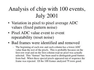
TDEC-5: Partial FA blockage • ASSUMPTIONS: • Total ΔP over the FA = 1.0 bar • ΔP at FA inlet = 0.22 bar • Partial flow area blockage at FA inlet • No heat exchange with surrounding FAs • MAIN RESULTS: • 75% FA flow area blockage 50% FA flowrate reduction • 85% blockage T-max clad = 700 °C • No clad melting if area blockage < 95% • Fuel melting if area blockage > 97.5% • 50% inlet flow area blockage can be detected by TCs at FA outlet 18
Conclusions • The analysis of DEC transients with RELAP5 code has highlighted the very good intrinsic safety features of ALFRED design thanks to: • Good natural circulation characteristics, • Large thermal inertia, and • Prevalent negative reactivity feedbacks • In all analyzed transients there is no risk for significant core damage or risk for lead freezing large grace time is left to the operator to take the opportune corrective actions and bring the plant in safe conditions in the medium and long term • The RELAP5 results for unprotected transients (UTOP, ULOF, ULOHS and ULOHS+ULOF) are confirmed by the results of the analyses performed with the CATHARE code 19