Download

1 / 10
100 likes | 333 Views
October 5, 2013. Proportional, Integral, Derivative Line Following. Welcome and Introductions. Line Following. Why is line following useful in FLL? Wide black lines with surrounding white area can be used for successful navigation.

E N D
October 5, 2013 Proportional, Integral, Derivative Line Following
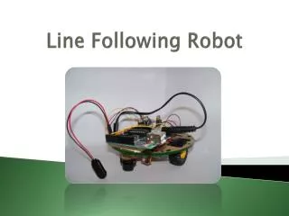
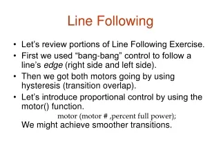
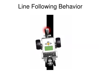
Line Following • Why is line following useful in FLL? • Wide black lines with surrounding white area can be used for successful navigation. • Light sensor is preferable to color sensor due to: (a) higher resolution, and (b) ability to calibrate. • As with all line following, steering the robot is accomplished by independently controlling the power of the left and right motors. The motors work to keep the light sensor at the edge of the line.
What is PID? A PID (Proportional, Integral, Derivative) controller is a common technique used to control a wide variety of machinery including vehicles, robots, and rockets. A PID controller compared to a standard 2 and 3 level line follower. The x - axis is the light sensor reading. The y - axis is the amount of turn. Note that the threshold for the 2 level and 3 level line following is 50. PID
We will construct a PID line follower which… • Moves the robot forward. • Uses light sensor in port 2 to follow the line. • Follows the left-hand-side edge of the line. 2 B C
PID Pseudocode – Initial variables to be used • Let “Kp” = some number • Let “Ki” = some number • Let “Kd” = some number • Let “Tp” (target power) = some power level • Let “Integral” = 0 • Let “Derivative” = 0 • Let “Last Error” = 0
Pseudocode – some calculations to perform • Reset rotation sensor B • Begin Loop • Let “Error” = light sensor intensity reading – (minus) 50 • Let “Integral” = “Error” + (plus) “Integral” • Let “Derivative” = “Error” – (minus) “Last Error” • Let “PTerm” = “Kp” x (times) “Error” • Let “ITerm” = “Ki” x (times) “Integral” • Let “DTerm” = “Kd” x (times) “Derivative” • Let “Turn” = “PTerm” + “ITerm” + “DTerm” • Let “Turn” = Turn / (divided by) 100 • Let “PowerB” = “Tp” + (plus) “Turn” • Let “PowerC” = “Tp” - (minus) “Turn” • Let “LastError” = “Error”
Pseudocode – establish power levels • If “Power B” > 0, then motor block B forward unlimited at “Power B” power level, • else motor block B reverse unlimited at negative “Power B” power level but with direction or movement reversed (We want a negative number to mean that the motor should reverse direction. But the data port on a NXT-G MOTOR block does not understand that. The power level is always a number between 0 and +100. The motor's direction is controlled by a different input port. Negative motor power needs to be made into a positive number and the motor direction needs to be reversed on the control panel • If “Power C” > 0, then motor block C forward unlimited at “Power C” power level, • else motor block CB reverse unlimited at negative “Power C” power level but with direction or movement reversed • End Loop • Stop Motors C and B