Download
1 / 25
250 likes | 455 Views
Booster Beam Notching Overview for 2012. December 7, 2011. S. Chaurize. Current Notching in 2011. A 3 bucket gap is created using two kickers located at Long 5 and Long 12 Notcher – A High Voltage(55kV) Kicker at Long 5 Noker - Lower Voltage Kicker (20-40 kV) at Long 12

E N D
Booster Beam Notching Overview for 2012 December 7, 2011 S. Chaurize
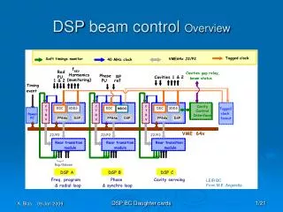
Current Notching in 2011 • A 3 bucket gap is created using two kickers located at Long 5 and Long 12 • Notcher – A High Voltage(55kV) Kicker at Long 5 • Noker - Lower Voltage Kicker (20-40 kV) at Long 12 • Used to clean out remnant Notched Beam in buckets At 700 MeV • Beam is kicked vertically into collimator region at Long 6 and Long 13 with upstream gradient magnets seeing some deposited notched beam loss. • The notch timing and synchronization is accomplished by modules in the Booster LLRF Room and local timing modules. • Beam notch for non-cogged cycles occurs at 400 Mev • Cogged notch occurs close to 700 MeV
Notching in 2012Phase 1 • A 3 bucket gap is created using three Long kickers located at Long 12 • 3 Notcher – High Voltage(46kV) Kicker at Long 12 • Notcher converted to Notch1 • Noker converted to Notch2 • Build/Commission new Notch3 mostly with parts on hand. • Beam is kicked verticallyHorizontally At L12 into new absorber at Long 13 • The notch timing and synchronization is accomplished by modules in Booster LLRF Room. (Same as before) • Beam notch for non-cogged cycles occurs at 400 Mev. (Same as before) • Cogged notch occurs close to 700 MeV. (Same as before)
The Notch 3 Bucket Notch Width non-cogged Cycle Notch @ 400MeV Cogged Cycle Notch@ ~700MeV Extraction Loss
L5 Notcher Current LocationNotcher magnet will be moved to L12Vertical Pinger magnet will be removed from L12 and put here in its place Hor. Pinger Notcher
L5 NotcherPower supply components such as theseWill need to be moved to support Long 12 region CX1168 tube cabinet CX1168 tube Low Level equipment
L12 Noker Current Location Noker Beam direction
L12 Noker Current Location MKS04 Ver. Pinger Noker De-commissioned Horz. Pinger Beam direction
L12 Noker Current Location MKS04 Notch3 Notch2 Notch1
L12 Noker& Extraction Kicker MKS04Power supply components such as thesewill need to be installed/relocated to support notch2 & notch3in east Booster Gallery CX1168 tube cabinet Beam sync Modules and other NIM crate Support modules.
Long 13 Current Noked beam absorber Beam direction
Long 13 Current Noked beam absorber Beam direction
Notching in later 2012-BeyondPhase 2 • Convert 3 Long kicker magnet notchers to short doublets magnets • 6 short style kicker magnets would be driven by faster thyratrons to allow quicker fill times creating a cleaner notch • 2 short magnets will mount in the foot print of one long magnet(current) kicker.
Short Kicker/Long kicker (25 ohm setup) on CX1168 Thyratron tube test-setup. ShortKick (Short Kicker) Rise = 21nS Fall = 33nS MKS04 (Long Kicker) Rise = 30nS Fall = 50nS Typical Booster kicker rise time 40 ns J. Lackey, R. Mraz, S. Chaurize
Conclusion • Phase 1 of new notching scheme should reduce extraction losses with a cleaner notch still using long kicker modules. • Losses will be better directed to a more optimized absorber close to the notching kickers. • Phase 2 will implement faster rise kicker modules to further reduce losses. • With higher beam throughput in 2012 and beyond this new notch system configuration should help reduce losses and minimize activation of critical areas in the Booster enclosure.
31”” 10”
30” 30” 12’-3 ” 96” 24” 18’-11 ” 75” 10 ‘ All Measurements Approximate