Download
1 / 22
220 likes | 368 Views
Dynamic Domain Architectures for Model Based Autonomy. MoBIES Embedded Software Working Group Meeting April 10-11 2001. B. Williams, B. Laddaga, H. Shrobe, M. Hofbaur MIT Artificial Intelligence Lab Space Systems Lab. Mode Estimation and Fault Diagnosis.

E N D
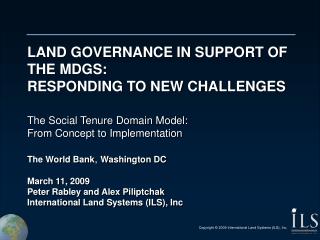
Dynamic Domain Architectures for Model Based Autonomy MoBIES Embedded Software Working Group Meeting April 10-11 2001 B. Williams, B. Laddaga, H. Shrobe, M. Hofbaur MIT Artificial Intelligence Lab Space Systems Lab
Mode Estimation and Fault Diagnosis Karl Hedrick in Automotive Powertrain OEP Overview: “Powertrain control system software for automotive application is becoming more and more complex due to increasing functionality as well as ever more wide-ranging onboard diagnostic systems mandated by state and federal governments.” • Challenge Problem: Model-based synthesis of an onboard monitoring and diagnostic engine that determines the (fault) mode of the powertrain system based on sensor data and the powertrain model. • Model-based: • Mode estimates (diagnoses) generated from component-based models. • Handles multiple faults and multiple symptoms. • Focuses on most likely modes (faults). • Handles un-modeled failures / situations.
Fault Scenarios: Intake System • Throttle/Intake Faults: • (partially) clogged • stuck-at • intake leak • … • EGR Valve Faults • stuck-at • valve leak • Intake Manifold Pressure Sensor • binary faults: stuck-at • soft faults: drifting, noise • … VDL powertrain model
Diagnostic Approaches: • Livingstone (Mode Estimation and Repair) • Models = probabilistic automata + discrete constraints. • Performs extensive deduction online. • MiniMe (Miniature Mode Estimation) • Component models = discrete constraints • Precompiles diagnoses of individual symptoms. • Combines diagnoses on line. • HybridME (Hybrid Mode Estimation) • Models = probabilistic hybrid automata • detects degradation and incipient faults
Experiments for FY01 Milestones • Implement MiniME and HybridME v1 modules. • Validate Livingstone and MiniMe based on the simulated Intake Subsystem of the Powertrain OEP: • Intake/Throttle faults • Pressure and Airflow sensor faults FY02 Program Milestones • Extend HybridME to concurrent automata. • Validate HybridME based on the simulated Intake Subsystem of the Powertrain OEP model • Validate intake subsystem diagnosis experiments on real-world data.
Success Criteria: • Detection of incipient failures • Detection of novel failures • Real-time performance • Use of both discrete and continuous models • Demonstration on simulated data. • Demonstration on real world data
Open Issues Need: • sensor / actuator models • Realistic fault scenarios and fault models • Realistic sensor placement for power train • Model of linkage from actuator to engine (e.g, by wire?) • Model for EGR control • Faults that may be injected within the real world OEP powertrain (e.g., valve and intake leaks)?
Livingstone: Model-based Mode Estimation and Reconfiguration Thrust Goals Delta_V(direction=b, magnitude=200) Power Point(a) Attitude Off Engine Off Flight System Control RT Control Layer Temporal planner State goals Livingstone Observations Command
Thrust Goals Delta_V(direction=b, magnitude=200) Valve Power Stuck open 0.01 Open 0. 01 Point(a) Attitude Open Close 0. 01 Stuck closed Off Engine Off Closed 0.01 inflow = outflow = 0 Model Flight System Control RT Control Layer Temporal planner State goals Livingstone Observations Command
Thrust Goals Delta_V(direction=b, magnitude=200) Power Point(a) Attitude Off Engine Off Model Flight System Control RT Control Layer Temporal planner State goals Livingstone mode = open high pressure = high flow; nominal pressure = nominal flow; . . . mode = closed Zero flow Observations Command
State estimates Configuration goals Thrust Goals Delta_V(direction=b, magnitude=200) Mode Estimation Mode Reconfiguration Power Point(a) Attitude Off Engine Off Model Flight System Control RT Control Layer Temporal planner State goals Livingstone Observations Command
Reactive Model-based Programming (RMPL) Thrust Goals Delta_V(direction=b, magnitude=200) Open four valves Power Point(a) Attitude Off Engine Off Valve fails stuck closed Fire backup engine Model Flight System Control RT Control Layer Temporal planner State goals Livingstone Observations Command
Model based Diagnosis (GDE) • Conflict Recognition • A symptom is a discrepancy between the model and observations. • A conflict is a minimal set of component modes that is inconsistent with the observations. • Conflict Recognition produces ALL conflicts. • Candidate Generation • A diagnosis is an assignment of component modes that resolves all conflicts. • A kernel diagnosis is a minimal set of component modes that resolves all conflicts. • Candidate generation produces the likely kernel diagnoses
Miniature Mode Estimation (MiniME) Idea: Generate Conflicts offline: • Compile time: • - Given component models and interconnections. • - Generates rules mapping observations to conflicts. • Run time: • Rules select conflicts based on current observations. • Generate most-likely kernel diagnoses from conflicts.
Hybrid Probabilistic Automata model M … set of discrete modes x, u, y … continuous state, input, output F … continuous dynamics for each mode (ODE) T … probabilistic transitions between modes • Probabilistic transitions: • Go to a nominal or failure mode • Are conditioned on continuous variables HybridME Compiler Compiler maps RMPL Model to concurrent Hybrid Probabilistic Automata. • A Hybrid Probabilistic Automata (HPA) encodes a hidden Markov model. • Modes exhibit a continuous dynamical behavior, expressed by differential or difference equations.
HybridME Mode Estimator Hybrid State Estimator maintains a set of likely hybrid state estimates as a set of trajectories. • Hybrid mode estimator • determines possible mode transitions for each trajectory. • selects candidate trajectories to be tracked by the continuous state estimators. HMM belief state update is used to determine the likelihood for each traced trajectory
Techsat-21 Mission • 3 spacecraft reconfigurable constellation • High relative positioning accuracy (3mm-1cm) • 28.5 inclination orbit (+/- 20 deg lat) • 90 minute orbit, 1-day ~repeat track • Each spacecraft has an X-band radar • Est. 1m resolution (range and x-range) • Non-repeat pass interferometry possible due to simultaneous emission and receipt of all 3 s/c using orthogonal waveforms • Not used for ASC demonstration due to computational cost of onboard processing • Backscatter of X-band wavelength can easily distinguish water, ice, land (fresh v. old lava)
Autonomous Science Constellation Mission Concept 1. Target Imaged 2. ScienceEventDetected 3. Re-Plan 5. New Science Images taken(repeat track) 4. Constellation Reconfigured
Key Technologies • Cluster Management (PSS/AFRL) • Enables single interface to cluster • Robust Execution (ICS/AFRL) • Enables plans to deal wit run-time uncertainties • Model-based Mode Identification and Reconfiguration (MIT SSL) • Enables timely state estimation and low level control • Onboard Science (JPL) • Feature detection & pattern recognition • Change detection • Enables onboard science decision-making • Onboard Replanning (JPL) • Enables onboard development of new plans to perform observations
Technology Impact • Enable vast improvements in science for fixed downlink • Downlink only highest science value images • Enable observation of short-lived science events • Reduce downtime due to anomalies • Reduce setup time via exploitation of execution feedback
ASC DemonstrationSoftware Message Detail Diagram 8.4. Commands from SCL (FORM_IMAGE, PROCESS_IMAGE) 2. Goals from ground (UPDATE_GOALS) 6. Cancelled goals from CASPER (ACTIVITY_DELETE) 8. Commits from CASPER (ACTIVITY_EXECUTE) 8.1 Maneuver commands from OA (TBD) 8.1 Response from OA (FORMATION_COMPLETE) 8.2 Radar point commands from OA (TBD) 8.2 Response from OA (RADAR_POINTED) 8.4 Response from Science (IMAGE_FORMED, IMAGE_PROCESSED) 8.4 Goals from Science (IMAGE, DOWNLINK, CACHE_IMAGE) 9. r/s/a updates from SIM 8.4 Response to SCL (IMAGE_FORMED, IMAGE_PROCESSED) 8.4. New goals to SCL (IMAGE, DOWNLINK, CACHE_IMAGE) Bus mirroring provided by ICS Science 5. Cancelled goals to SCL (ACTIVITY_DELETE) 8. Activity commits to SCL (ACTIVITY_EXECUTE) 8.1 Request to OA (COMPUTE_FORMATION) 10. Time to all (TIME) 3. Goals to CASPER (ACTIVITY_CREATE) 8.1 Command to OA (CHANGE_FORMATION) 8.1 Maneuver commands to Broadreach (TBD) 8.2 Command to OA (POINT_RADAR) 8.2 Radar point commands to Broadreach (TBD) 8.3 Commands to SIM (SAR_ON, CALIBRATE, TAKE_DATA, METROLOGY) 8.4 Commands to Science (TRANSFER_SAR_DATA, FORM_IMAGE, PROCESS_IMAGE) 8.4 Goals to CASPER (UPDATE_GOALS) 9. r/s/a updates to CASPER (RESOURCE_UPDATE, STATE_UPDATE, ACTIVITY_UPDATE) CASPER Solaris s/w bus OSE s/w bus SCL 4. Goals from SCL (ACTIVITY_CREATE) 8.1 Response from OA (FORMATION) 8.4 Goals from SCL (UPDATE_GOALS) 9. r/s/a updates from SCL (RESOURCE_UPDATE, STATE_UPDATE, ACTIVITY_UPDATE) 8.1 Request from CASPER (COMPUTE_FORMATION) 8.1 Command from SCL (CHANGE_FORMATION) 8.2 Command from SCL (POINT_RADAR) OA SIM Burton DynamicsSIM 8.1 Responses to CASPER (FORMATION) 8.1 Responses to SCL (FORMATION_COMPLETE) 8.1 Maneuver commands to SCL (TBD) 8.2 Response to SCL (RADAR_POINTED) 8.2 Radar point commands to SCL (TBD) 8.3 Commands from SCL (SAR_ON, CALIBRATE, TAKE_DATA) 9. r/s/a updates to SCL Solaris OSE r/s/a = resource, state, activity
Validation Plan BurtonFDIR CASPERPlanner SARImage Formation OnboardScience SCL Execution Autonomy ObjectAgent TeamAgent Cluster Mgmt Unit Testing on relevant data Study Phase April 2000 Integration on Workstations ASC Experiment System Testing on relevant data Sep 2000 ASC System Demonstration on Workstations Broadreach Low-level FSW ASC Transition toAFRL Testbed March 2002 System Demonstration on AFRL Techsat-21 Testbed 9-02 Refinement Phase ASC Transition toFlight Hardware System Demonstration on Techsat-21 Flight Hardware September 2003 ASC Flight September 2004 Techsat-21 Flight Demonstration Gates