Download
1 / 19
190 likes | 293 Views
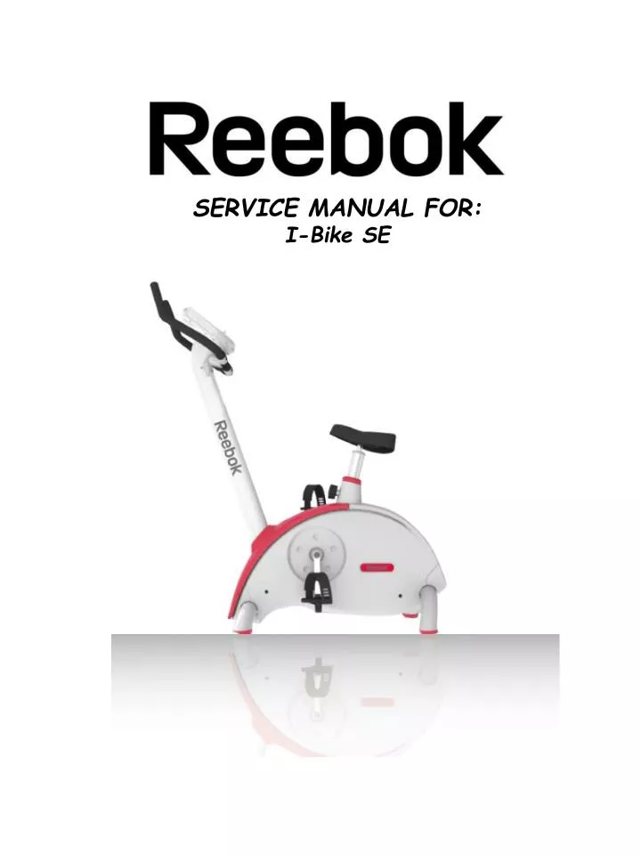
SERVICE MANUAL FOR: I-Bike SE. Specifications. Set up dimension: 110X55X129mm Fold up dimension: No Weight of product: 29kg Shipping Weight: User weight limit: 120kg Resistance Level: 1-16 levels Incline Range: No Hand Pulse Sensor: Yes Wireless Pulse Sensor: No

E N D
SERVICE MANUAL FOR: I-Bike SE
Specifications Set up dimension: 110X55X129mm Fold up dimension: No Weight of product: 29kg Shipping Weight: User weight limit: 120kg Resistance Level: 1-16 levels Incline Range: No Hand Pulse Sensor: Yes Wireless Pulse Sensor: No Power Requirement: UM-3 AA 1.5v X 2 Motor: No Emergency Stop: No
Remove Chain covers Step 1: First use a flat screwdriver to remove crank disc plastic covers, then use 14mm socket wrench to undo crank nut. Step 2: Use a crank remover tool to undo crank arm. Crank remover tool Step 3: on the other side, again use a flat screwdriver to remove crank disc plastic cover then use 14mm socket wrench undo crank nut. Step 4: Use a crank remover to undo crank. Step 6: Remove Front stabilizer tube cover. Step 5: lift off Chain cover upper cover.
Step 7: Use a Phillips screwdriver to undo Main chain Cover right screws x 4. Step 6: Remove Rear stabilizer tube cover. Step 9: Use a Phillips screwdriver to undo Main chain Cover left screws x 2. Step 8: Remove Main chain cover right. Step 9: Remove Main chain cover left.
Remove flywheel set Step 1: Follow Remove chain cover instruction to remove both chain covers. Step 2: Remove belt tension spring. Step 3: Remove the driver belt. Step 4: Use 3mm Allen wrench to undo flywheel fix bolts x 3 on the right side. Step 5: Use 3mm Allen wrench to undo flywheel fix bolts x 3 on the left side. Step 6: Flywheel can now be removed.
Disassemble flywheel Step 1: Follow Remove chain cover instructions to remove both chain covers. Step 2: Follow Remove flywheel set instructions to remove flywheel set. Step 3: Use 8mm Allen wrench to undo the centre bolt in the flywheel. Step 4: Remove flywheel Aluminum support insert. Step 5: Use 4mm Allen wrench to undo the Aluminum disk bolts x 4. Step 6: Flywheel can now be completed dismantled
Disassemble resistance bracket set Step 1: Follow Remove chain cover instructions to remove both chain covers. Step 2: Use a 5mm Allen wrench and 10mm Socket/spanner to undo magnet bracket top bolt and nut x 1. Step 3: Remove magnet bracket axle and spring. Step 4: Use a 6mm Allen wrench and 17mm Socket/spanner to undo magnet bracket bottom not and bolt x 1. Step 5: Magnet bracket can now be removed. Step 6: When reassembling the magnet bracket. You must ensure That the spring , thin washer and thick washer are installed as above
Remove resistance motor set Step 1: Follow Remove chain cover instructions to remove both chain covers. Step 3: Use 5mm Allen wrench, a 10mm and 13mm spanner/socket to undo magnet bracket Nuts and bolts. Step 4: Disconnect all wires from the resistance motor then remove the resistance motor from machine.
Engineer mode setting Enter Engineer Mode: Press and hold RESISTANCE UP and DOWN together, whilst holding insert power cable. The computer wil enter Engineer Mode, the SPEED display window will display the computer software version and the RPM display window will show 1. Set computer speed and distance based on wheel size: After entering Engineer Mode and SPEED display window is showing “1”, press START button. Use RESISTANCE UP and DOWN buttons to select between “78” and “56”, then STOP button to confirm and Press FITNESS button return power status. Value “78” for I-Bike SE Value “56” for I-Trainer SE Calibration resistance level Lo and Hi position: Attention: All console resistance ranges are factory default set, this function is for service technicians only, otherwise magnet bracket will stick or rub on the flywheel disk. After entering Engineer Mode use resistance up or down until SPEED display window shows “2”, then press START button. Computer TIME window will display “Lo”. Use RESISTANCE UP and DOWN buttons to adjust resistance Lo level magnet bracket position then press STOP button, after STOP is pressed computer will show “Hi”, then use RESISTANCE UP and DOWN button to adjust resistance Hi level magnet bracket position then press STOP button to confirm and Press FITNESS button return to power on status.
Converter display from Metric to English: After entering Engineer Mode use resistance up or down until SPEED display window shows “3”, then press START button, use RESISTANCE UP and DOWN button to select between “KM” or “ML” then press STOP button to confirm, KM/ML will disappear from screen, then Press FITNESS button return power status. – The setting is changed. Select I-Bike SE or I-Trainer SE console: The console for I-Bike SE and I-Trainer SE hardware and software are the same, but because I-Bike SE resistance motor VR track reverse, so must connect “05” jump point be I-Bike SE console, disconnect “05” jump point be I-Trainer SE console.
Trouble shooting NO RESISTANCE REPAIR There is no resistance after Start is pressed or 30 seconds? Computer does not display RPM during workout? YES NO YES Press START button then press Resistance UP button and test motor + and – voltage At same time . Check 7pin connector In upright tube? BAD DC ±6-9v Reconnect Replace resistance motor GOOD DC 0V Check RPM sensor Is Within 5mm of the Magnet on crank wheel. Press START Button then press Resistance UP button and test VR PC board pin3 and pin4 motor + and – voltage At same time . DC ±6-9v YES Replace resistance VR PC board Replace RPM sensor DC 0V Check 7pins connector In upright tube? BAD Reconnect GOOD Replace computer
110/230 VAC at outlet NO CHECK HOME CIRCUIT BREAKER YES Pull out Connector at unit Is adaptor has output voltage at metal connector ? DC 0V Replace Adaptor NO DISPLAY REPAIR DC 9-11V Check 7pins connector In upright tube? BAD Reconnect GOOD does JP1 connector have voltage at VR PC board? DC 0V Replace DC power Cable from chain plastic cover to VR PC board DC 9-11V Replace resistance motor set