Download
1 / 24
240 likes | 438 Views
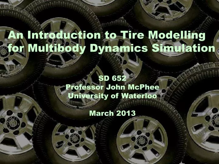
An Introduction to Tire Modelling for Multibody Dynamics Simulation. SD 652 Professor John McPhee University of Waterloo March 2013. Acknowledgement:.

E N D
An Introduction to Tire Modelling for Multibody Dynamics Simulation SD 652 Professor John McPhee University of Waterloo March 2013
Acknowledgement: Kevin Morency, Automatic Generation of Real-Time Simulation Code for Vehicle Dynamics using Linear Graph Theory and Symbolic Computing, MASc Thesis, University of Waterloo, 2007
Rolling Resistance (My) Produced by hysteresis in tire tread and sidewall rubber My = (Fz)(x)
Braking Force (Fx) S = (V – wR) / V 0 < S < 1
Braking Force (Fx) S = (V – wR) / V 0 < S < 1 Longitudinal Stiffness, CS, is the slope of the Fx vs. S curve at S=0
Driving Force (Fx) S = (wR-V) / wR 0 < S < 1
Lateral Force (Fy) and Aligning Moment (Mz) Cornering Stiffness, C, is the slope of the Fy vs. curve at =0
Characterizing a Pneumatic Tire: Physical Testing
Characterizing a Pneumatic Tire: Physical Testing
Data From Physical Tests Consider how Fx varies with S: 20 data points Consider how Fx varies with Fz, S,, : 204= 160 000 data points Consider how Fx varies with Fz and S: 202= 400 data points x5 = 800 000 data points
Pacejka 2002 : 117 parameters needed • Very good fit to experimental data • More complicated force and moment equations Tire Models: Mathematical Functions to Fit Measured Data Fiala: 6 parameters needed to describe a tire • Easy to understand the physical significance of all parameters • Simple force and moment equations. • Does not handle combined slip • Effects of normal force and camber are largely ignored.
C2 C1 P2 P1 How Tire Forces are Included In Multibody Vehicle Model 1. Define a point where tire forces and moments will act on the multibody model
How Tire Forces are Included In Multibody Vehicle Model 2. Determine an expression for the vertical tire force, Fz, which is required as an input to the tire model.
How Tire Forces are Included In Multibody Vehicle Model 3. Establish vector directions for longitudinal and lateral components of tire force.
How Tire Forces are Included In Multibody Vehicle Model 4. Determine kinematic inputs to tire model (S, , ) 5. Use a tire model to calculate Fx, Fy, Mx, My, Mz
The Fiala Tire Model The original tire model in MSC.ADAMS • Inputs: • Multibody model (mass, rotational inertia) • 2. Tire parameters (Cs, C, etc.) • 3. The current kinematic state(S, ,, etc.)