Download

1 / 127
1.28k likes | 1.32k Views
Heat Pump phase Part two. The outdoor section. Now that we’ve checked our thermostat and air handler, we’re ready to check the outdoor unit. The outdoor section. Setting the outdoor unit on the shipped with ISO pads, will help reduce sound transmission through the ground.

E N D
Heat Pump phase Part two
The outdoor section Now that we’ve checked our thermostat and air handler, we’re ready to check the outdoor unit.
The outdoor section • Setting the outdoor unit on the shipped with ISO pads, will help reduce sound transmission through the ground. • The concrete pad should not be touching the structure, for this same reason. • The unit should be set to prevent air re-circulation across it’s coil. See the installation instructions for that unit.
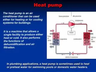
HEAT PUMP REVERSING VALUE ILLUSTRATION
SUCTION LINE OUT DOOR COIL INDOOR COIL . . . TP-4 TP-2 TP-3 . TP-1 COMPRESSOR DISCHARGE
TO ACCUMULATOR TO INDOOR COIL FROM OUTSIDE COIL . . . TP-4 TP-2 TP-3 . FROM COMPRESSOR DISCHARGE LINE 5F MAX TEMP. DIFFERENCE TP-1 HEATING MODE
TO ACCUMULATOR FROM INDOOR COIL TO OUTDOOR COIL . . . . . . . TP-4 TP-3 TP-2 . . . TP-1 FROM COMPRESSOR DISCHARGE LINE 5F MAX TEMP. DIFFERENCE COOLING MODE
COOLING CONDITION INDOOR COIL SAT. SUCT. T. 41F ENT. AIR T. 76F 4-WAY VALVE SUCT. P. 70 PSIG SUCT. T. 52F SUPERHEAT 11F METERING DEVICE SUBCOOLING 10F DISCHARGE PRESSURE 260 PSIG OUTDOOR COIL SAT. COND. T. 120F ENT. AIR T. 90F COMPRESSOR
HEATING CONDITIONS INDOOR COIL SAT. COND. T. 95F ENT. AIR T. 70F 4-WAY VALVE METERING DEVICE SUBCOOLING 10F METERING DEVICE SUBCOOLING 10F SUCT. P. 43 PSIG SUCT. T. 35F SUPERHEAT 10F DISCHARGE PRESSURE 182 PSIG OUTDOOR COIL SAT. SUCT. T. 20F ENT. AIR T. 45F COMPRESSOR
HEAT PUMP • TOTAL HEAT REJECTED EQUALS HEAT ABSORBED + HEAT OF COMPRESSOR
HEAT PUMP • METERING DEVICES • HEATING CYCLE, REFRIGERANT IS METERED TO THE OUTDOOR COIL • COOLING CYCLE, REFRIGERANT IS METERED TO THE INDOOR COIL
HEAT PUMP • METERING DEVICES • REFRIGERANT METERED TO COIL WHICH ABSORBS HEAT • HEATING CYCLE REFRIGERANT METERED TO OUTDOOR COIL • COOLING CYCLE REFRIGERANT METERED TO INDOOR COIL
METERING DEVICES • CAPTUBE • FIXED ORFICE • TXV
METERING DEVICES FLOW BYPASSES METERING DEVICE CHECK VALVE OPEN METERING DEVICE FLOW IS METERED CHECK VALVE SHUT METERING DEVICE
The outdoor coil Not in your books • Spine fin coil is used for it’s efficiency. • The majority of all heat transfer is done on the leading edge (the tip, where the air and coil first come into contact) of the fin. • A spine fin coil is much more efficient than a plate fin coil. So much so that it can do the same job with much less refrigerant. • Spine fin coils can easily be repaired.
The outdoor coil Not in your books • As mentioned earlier the outdoor coil will produce run off during defrost. • This water is normal and has not been known to cause damage in the past! • This water must drain freely from the unit. Any sort of drain/collection system would need to have some form of a heater to keep from freezing up and damaging the outdoor coil.
The role of the defrost control • To extract heat from the outdoor air, the heat pump must lower it’s outdoor coil temperature below that of the outdoor ambient. • Depending on the humidity and temperature, frost may form on the outdoor coil. • This frost will insulate the coil from the outdoor air, reducing it’s ability to absorb the heat from the outdoor air.
HEAT PUMP DEFROST CONTROLS • - CONTROLS THE DEFROST CYCLE IN A HEAT PUMP DURING HEATING OPERATION. • - THE DEFROST CONTROL CONTROLS THE FOLLOWING FUNCTIONS: • 1 - SWITCH OVER VALVE OR REVERSING VALVE • 2 - OUTDOOR FAN MOTOR • 3 - ELECTRIC OR GAS AUX. HEAT • 4 - INDICATES A FAULT HAS OCCURRED (OPTIONAL) • - CONTROL THAT ESTABLISHES THE NEED FOR A DEFROST • - BOTH TIMED AND DEMAND CONTROLS ARE USED TODAY • - ELECTRO MECHANICAL TIMERS AND PRESSURE SWITCHES USED IN THE PAST
Heat pump defrost controls • Several types of defrost controls have been used through the years. • We will discuss their function and diagnostics of each type. • The newer solid state and Demand Defrost controls will be the main focus of our time today.
DEFROST CYCLE • SYSTEM IN COOLING MODE- -ENERGIZE REVERSING VALVE • DIRECTS HOT GAS TO OUTDOOR COIL TO MELT THE FROST
As the frost accumulates on the outdoor coil, the systems capacity is reduced. • To remove the frost/ice from the outdoor coil, the system will shift itself into a variation of the cooling mode. • During a defrost cycle the outdoor fan will stop, leaving the heat in the coil to remove the frost. • The type of defrost control system will dictate how much frost/ice is allowed to accumulate prior to initiating a defrost.
DEFROST CYCLE • TEMPERING INDOOR AIR • ELECTRIC HEAT IS TURNED ON TO TEMPER THE AIR DURING DEFROST CYCLE.
DEFROST CONTROLS • THE MUCH OLDER EQUIPMENT UTILIZED ELECTRO-MECHANICAL TIME CLOCKS. • ELECTRONIC TIMER - TIME & TEMPERATURE DEFROST • SOLID STATE - DEMAND DEFROST
DEFROST CYCLE • OUTDOOR FAN OFF • ENHANCES DEFROST
Electro-Mechanical systems • All electro-mechanical systems are a “time/temperature” based control. • A predetermined amount of time must pass before a defrost cycle can be initiated. • As mentioned earlier, the outdoor conditions have major impact on the amount of defrost needed. • These systems are temperature activated as well.
Large amounts of frost may accumulate before the “Time” has elapsed. • This results in lower seasonal efficiency. • The reduced capacity will result with a greater dependence on a secondary heat source.
ELECTRONIC TIME-TEMPERATURE DEFROST CONTROL • 50 - 70 - 90 MINUTE COMPRESSOR RUN TIME SELECTION • 10 MINUTE TIME OVERRIDE IN DEFROST CYCLE • TWO TEST PINS - ADVANCES ELECTRONIC TIMER AND PUTS SYSTEM INTO DEFROST CYCLE FOR TESTING • ON BOARD DEFROST RELAYS FOR OUTDOOR FAN, SOV VALVE AND AUXILIARY HEAT • DEFROST TERMINATED ON TIME OR TEMPERATURE • COMPRESSOR RUN TIME IS KEPT ONLY WHEN COIL THERMOSTAT IS CLOSED
The defrost thermostat is set to close at 25º. • When the DT is closed, supplying 24 VAC to the D terminal, jumpering the test pins will speed up the internal clock. • If you are testing the system, and have a jumper from R to D, remove the jumper as soon as the system shifts into defrost to prevent excessive refrigerant pressures.
These controls will default to the 90 minute setting if the selector jumper is not connected. Which is how the equipment is shipped. • I recommend one of the shorter time settings, 50 or 70 minutes. • The water run off from a unit in defrost is pure water, and has never been reported to caused roof damage to date! • Trying to catch the water could damage the outdoor coil (if the collected water froze and backed up under the coil).
DFC CNT1152ORCNT1642 K2 1 K1 M1 ODFAN M2 90 70 50 TST EDR R R B B X2 Y O O D T 24V AC24V COMMON INDOOR THERMOSTAT MS SC CNT1152 may be replaced by CNT 1642 1 DT
DFCCNT1642 K2 K1 M1 ODFAN M2 90 70 50 TST EDR R R B B X2 Y O O DT T X2 INDOOR THERMOSTAT YOT SC EDR DT EDR 24V AC 24V COMMON ECONOMIZER(OPTIONAL) EDC OR LPCO MS F INDOORTHERMOSTAT G COMMON FORELECTRIC HEATER TR TR1
TST EDR R R B B X2 Y O O D T
TST EDR R R B B X2 Y O O D T
TST EDR R R B B X2 Y O O D T
TST EDR R R B B X2 Y O O D T
TST EDR R R B B X2 Y O O D T
TST EDR R R B B X2 Y O O D T
TST EDR R R B B X2 Y O O D T
There are several versions of these DFC boards. Many feature the exact same functions, with the only difference being the terminal for the defrost thermostat being labeled “D” or “DT”. TST EDR R R B B X2 Y O O D T
There are several versions of these DFC boards. Many feature the exact same functions, with the only difference being the terminal for the defrost thermostat being labeled “D” or “DT”. TST EDR R R B B X2 Y O O D T
There are several versions of these DFC boards. Many feature the exact same functions, with the only difference being the terminal for the defrost thermostat being labeled “D” or “DT”. TST EDR R R B B X2 Y O O D T
There are several versions of these DFC boards. Many feature the exact same functions, with the only difference being the terminal for the defrost thermostat being labeled “D” or “DT”. TST EDR R R B B X2 Y O O D T
There are several versions of these DFC boards. Many feature the exact same functions, with the only difference being the terminal for the defrost thermostat being labeled “D” or “DT”. TST EDR R R B B X2 Y O O D T
There are several versions of these DFC boards. Many feature the exact same functions, with the only difference being the terminal for the defrost thermostat being labeled “D” or “DT”. TST EDR R R B B X2 Y O O D T
DEMAND DEFROST • FEATURES • ADAPTABILITY • LEARNING PROCESS • DEFROST ON DEMAND • DIAGNOSTICS • TIME OVERRIDE • SOFT SWITCHOVER