Download
1 / 54
540 likes | 664 Views
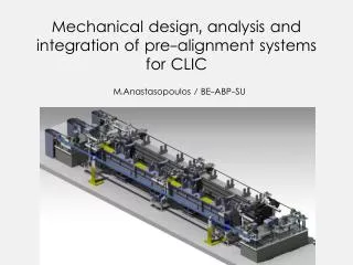
STATUS OF THE CLIC PRE-ALIGNMENT STUDIES. Survey and alignment for CLIC. For the CLIC project, Survey people will have to align (measure the position and adjust) all beam components or their associated supports:

E N D
STATUS OF THE CLIC PRE-ALIGNMENT STUDIES H. MAINAUD DURAND, BE-ABP/SU, 23/04/2010
Survey and alignment for CLIC • For the CLIC project, Survey people will have to align (measure the position and adjust) all beam components or their associated supports: • In all the area of the tunnels (Main beam injectors, drive beam generation complex, main linac, Beam Delivery System, return loops,…) • ≈ 72 000 components or supports (data on Sept. 2007) • ≈ 52 km (data on Sept. 2007) • On the ground, on the ceiling (transfer lines), in loops (return loops, damping rings) • Within various tolerances ranging from 10 microns to 300 microns.
Survey and alignment studies Some priorities have been given concerning the survey and alignment studies: • Prove the feasibility of the pre-alignment of the components of the main linac within a tolerance of 10 microns over a sliding window of 200m along the whole linac • Propose a solution for the pre-alignment of the CLIC final focus (QD0) • Propose a global solution of alignment • Integrate this solution and make it compatible with other services.
SUMMARY • General strategy and required solutions • Introduction of the challenge and hypotheses considered for the studies • General strategy • Required solutions • R&D program and first results • Solutions for the determination of position • Solutions for re-adjustment • Special case of MDI area • Solution proposed for the CDR • Studies proposed for the TDR
Introduction of the main challenge PRE-ALIGNMENT (beam off) Mechanical pre-alignment Active pre-alignment Beam based alignment Beam based feedbacks Within +/- 0.1 mm (1s) Within ± 10 mm (3s) Tolerance of 10 microns along a sliding window of 200m, all along each linac After computation, for a sliding window of 200m, the standard deviations of the transverse position of each component w.r.t. the straight fitting line must be inferior to 10 microns
Introduction: why active pre-alignment? At a micron scale: Ground motion Continuous determination of the position of the components Re-adjustment when necessary Noise of accelerator Temperature dilatations Considering the number of components supports to be aligned Considering the resolution of displacement required Determination of the position of the components in a general coordinate system thanks to alignment systems + = Active pre-alignment Re-adjustment thanks to actuators
Introduction: hypotheses for study 10 μm over 200m (3σ) is a target for study and development. « trade off » with beam dynamics for realistic and achievable values for CDR. Budget errors: RF structures: From D. Schulte, CLIC meeting, 04/05/2007.
Budget errors: MB quad: Budget errors: MB BPM: From D. Schulte, CLIC meeting, 04/05/2007.
Budget errors Main linacmoverrequirements Addressed by the Stabilization Working Group From D. Schulte, CLIC Module Review, 15/09/2010.
General strategy : re-adjustment • Several components will be pre-aligned on supports: • Along the MB: Along the DB: • RF structures on girders PETS + DB quad on girders • MB quad on interface plate DB and MB girders will be interlinked with their extremities, based on so-called cradle. This allows a movement in the transverse girder interlink plane within 3 degrees of freedom. (Longitudinal direction adjusted thanks to a mechanical guiding). MB quad is mounted on an interface plate, allowing an adjustment along 5 degrees of freedom (longitudinal position will be positioned manually).
General strategy: determination of the position of the components Installation and determination of the surface network Transfer of reference into tunnel Installation and determination of the tunnel network Absolute alignment of the elements Relative alignment of the elements Active pre-alignment For the main linac Control and maintenance of the alignment
General strategy: determination of the position of the components Geodetic Reference Network (GRN) Backbone for all the tunnels and areas Will allow the installation of all services and of the MRN 12
General strategy: determination of the position of the components Geodetic Reference Network (GRN) Metrologic Reference Network (MRN) • As it is not possible to implement a straight alignment reference over 20 km: use of overlapping references • Two references under study: • a stretched wire • a laser beam under vacuum 13
General strategy: determination of the position of the components Geodetic Reference Network (GRN) Metrologic Reference Network (MRN) Support Pre-alignment Network (SPN) 14
General strategy: determination of the position of the components Geodetic Reference Network (GRN) Metrologic Reference Network (MRN) Support Pre-alignment Network (SPN) Alignment and fiducialisation of each component on the supports (AFC) 15
Required solutions: feasibility of the concept ISSUES STEPS Stable alignment reference, known at the micron level Determination of the metrological network w.r.t the straight alignment reference Submicrometric sensors providing « absolute » measurements Determination of the position of each sensor w.r.t metrological network Fiducialisation: determination of the zero of each component w.r.t the sensor (external alignment reference) Activepre-alignment Measure 2m long objects within a few microns Re-adjustment: displacement of the component supporting structure according to the sensor readings Submicrometric displacements along 3/5 DOF Other issues: Compatibility with the general strategy of installation and operation Compatibility with other accelerator equipment or services 16
Required solutions: lessons from the past (1990->2002) • Feasibility of controlling submicron movement. • Development of sensors whose resolution is submicrometric • Development of alignment methods associated with these sensors (double stretched wire method) • Development of an active alignment system • Tests of the sensors and validation of an active alignment in a real environment (CTF2)
Required solutions: lessons from CTF2 In the CTF2 facility, the components (CAS, PETS) were maintained aligned in a closed loop w.r.t. a stretched wire within a window of ± 5 microns, thanks to sensors and micro movers, in a very radioactive environment. BUT… • Sensors and actuators were used for monitoring w.r.t a reference position and repositioning, not for pre-alignment • The pre-alignment in that case was manual and iterative (no fiducialisation : the position of the WPS was not known w.r.t the reference axis of the accelerating cavities) • Small scale solution to align the accelerating cavities on the girders • Mechanical design to update (modification of the size of the components considerable increase of load some question marks concerning the clearances and kinematics) • A solution of fiducialisation within a few microns must be found • A new solution of pre-alignment for the MB quad must be found (CTF2 solution not compatible with stabilization requirements)
Introduction: state of the art Monitoring requirements (after Beam Based Alignment ) and not pre-alignment (before BBA) Precision and not accuracy Precision over less than 200 m, during short periods No solution answering the requirements exists 19
Required solutions • In 2005, when the CLIC studies on pre-alignment re-started, the following directions of studies were proposed: • Concerning the measure of the position of the components: • Improvement of the stretched wire solution • Development of a laser based solution (as B-plan) • Find methods of fiducialisation and pre-alignment of the components on the supports • Concerning the re-adjustment: • Find a new solution for the re-adjustment of the MB quad • Re-design/R-sizing the cradle inter-linking two girders
SUMMARY • General strategy and required solutions • Introduction of the challenge and hypotheses considered for the studies • General strategy • Required solutions • R&D program and first results • Solutions for the determination of position • Collaboration with NIKHEF • LAMBDA project • Stretched wire solution • Solutions for re-adjustment • Special case of MDI area • Solution proposed for the CDR • Studies proposed for the TDR
Status of the different solutions No solution answering the requirements exists yet! Metrologic Reference Network (MRN) • Stretched wire, modelized in vertical with HLS system • Long range RASCLIC (NIKHEF) • Multi-point alignment system based on laser beam. Not ready for CDR Support Pre-alignment Network (SPN) • Stretched wire • RASNIK, short range RASCLIC (NIKHEF) • Multi-point alignment system based on laser beam. Not ready for CDR Alignment and fiducialisation of each component on the supports (AFC) 22
Collaboration with NIKHEF • 3 main objectives in 2005 : • A paper study on a low-cost RASNIK system to be implemented all along the linac as SRN (including an outlook for the relevant developments to be expected within the 10 years). • The development of a sub-nanometer RASNIK • The development of a laser alignment system, as MRN: • Capable of giving a « straight » reference on more than 100m, with an accuracy of a few micrometers. • Allowing to perform an inter-comparison with stretched wire measurements • And the study of its implementation along 40 km. Not addressed
Collaboration with NIKHEF • Results: • A resolution of position of 20 nm was reached in TT1 • The system appeared to be a very good low-frequency seismograph • On short distances, vacuum is no more needed: a « short range » RASCLIC could replace the RASNIK system foreseen as SRN. • Remaining issues: • Vacuum is needed on long distances, which implies a sophisticated mechanics between the component to be aligned and the RASLIC part • Configuration: must be implemented as « leap frog ». No flexibility when distances are not constant.
Collaboration with NIKHEF • Proposal for a new collaboration between CERN and NIKHEF around 3 WP: • Adapt the « long range » RASCLIC for CLIC and validate it • Calibration • Validation through an inter-comparison with stretched wires (in TT1, TZ32) • Adapt the « short range RASCLIC for CLIC configuration and validate it • Calibration • Validation through an inter-comparison on the two beam module prototype (in lab and in CLEX) • Propose a solution for the monitoring of the QD0 on both sides of detector.
LAMBDA Project • LAMBDA for Laser Alignment Multipoint Based – Design Approach • Technical note concerning the concept proposal ready • Preliminary study concerning the mechanical shutters will start soon • Definition of the subject for a doctorate student in progress
Stretched wire • Main issue: long term stability of a wire • (effects of temperature, humidity, creeping effects, air currents) • Modelization of the wire using Hydrostatic Levelling Systems (HLS) • but only in the vertical direction • but HLS system follows the geoid which needs then to be known • studies undertaken concerning the determination of the geoid • Is a stretched wire really straight (transverse direction)? • First idea: comparison with a laser beam under vacuum (NIKHEFF) • Inter-comparison of different types of wires and technologies • on short distances (50 m) this summer at SLAC • Subject of a thesis: « Determination of a precise gravity field for the CLIC feasibility studies » Sébastien Guillaume.
Stretched wire and MRN Minimum configuration TT1 facility • Objectives: • To determine the precision and accuracy of a MNR consisting of overlapping stretched wires • To study the behavior of wires of different lenghts • To study the modelization of a stretched wire • To build and validate the laser solution through an inter-comparison
Stretched wire and MRN First results in TT1 σ(rad)=0.4 µm , σ(vert)=0.6 µm for ΔT=0.2°C and Δhumidity=7.7% • Subject of a thesis: « Analysis and Modelling of the effect of tides on the Hydrostatic Levelling Systems at CERN » Julien Boerez.
Stretched wire and MRN Results on 500 m • Know-how developed for the installation of long wires (500 m)
Stretched wire and MRN Latest results in TT1 • Precision on 140 m wire: better than 2 microns over 33 days • Accuracy: 11 microns in vertical, 17 microns in radial. Can be improved! • Vertical residuals of the 2 longest wires: • σ (wire 1) = 1.6 µm • σ (wire 2) = 0.5 µm • Accuracy of the TT1 network adjusted by the least squares method in vertical: • σ = 11 µm r.m.s (27 µm max. value) • Subject of a thesis: « proposal of an alignment method for the CLIC linear accelerator: from the geodetic networks to the active pre-alignment » Thomas Touzé.
Sub-micrometric sensors • Issue: WPS sensor fulfilling the requirements • « absolute measurements » (known zero w.r.t mechanical interface) • no drift • sub micrometric measurements Capacitive based WPS (cWPS) Optical based WPS (oWPS) Upgraded WPS Resolution: 0.2 µm Range: 10 x 10 mm Repeatibility: 1 µm Bandwidth: 10 Hz
Inter-comparison between sensors: Web site: https://clic-pral.web.cern.ch/clic-pral/ • Status of the inter-comparison: • WPS [SLAC, CERN] : inter-comparison at SLAC. Facility ready in July 2010. • HLS [Fermilab, SLAC, DESY, SSRF]: long term stability tests at Fermilab, other tests at CERN.
Status of the different solutions Strategy towards the feasibility • Only one solution ready for CDR : stretched wire + WPS • cWPS: • design of a new mechanical interface and associated calibration bench improve the accuracy (target : accuracy < 5 μm) • cost study in definition for 50 000 units. • oWPS: • definition of the next generation under progress Stretched wire for MRN and SRN 35
Status of the different solutions Strategy towards the feasibility • Several studies launched to address the drawbacks of the WPS and stretched wire • Development of a concept allowing to stretch a wire without access to the sensors and the wire protection • A method was found to stretch two wires in the same optical sensor (to be validated on long distance) • Determination of the local deviation of vertical (so to have a perfect knowledge of the geoïd) 36
Simulations close to the reality • Objectives: • Find the best strategy and configuration of alignment systems for the pre-alignment • Model the impact of the pre-alignment errors on the beam emittance growth • First results: • The pre-alignment tolerance could be achieved with wires longer than 425m. • Beam simulations, based on these data showed that 400m wires were able to limit the long distance emittances. • Next steps implementation of a new model, closer to the reality • The requirements were defined in collaboration with the Beam Dynamics WG • These steps are now mathematically defined • The algorithms are being implemented and tested on the TT1 configuration (validation of the model on 150m) • Development of a software allowing the modeling on the whole CLIC. 37
Summary concerning the determination of the position of the components for the CDR On surface In the tunnel
SUMMARY • General strategy and required solutions • Introduction of the challenge and hypotheses considered for the studies • General strategy • Required solutions • R&D program and first results • Solutions for the determination of position • Solutions for re-adjustment • Strategy • Status • First results • Validation on mock-ups • Special case of MDI area • Solution proposed for the CDR • Studies proposed for the TDR
Strategy of re-adjustment MB Quad // cam movers DB and MB girders // linear actuators Validation of a SLS type cam mover (1 DOF mock-up) Re-installation of CTF2 re-adjustment solution Validation of on a 5 DOF mock-up Validation on a pre-alignment mock-up • Design of the mock-up (MME design office) • 5 high resolution cam movers ordered (ZTS) • Design of a new cradle (MME design office) • 9 high resolution linear actuators ordered this week (ZTS) Validation on the two beam module prototype Validation on the two beam module prototype • DR approved by the finance commitee • Market Survey to be prepared and sent • Cost for 5 cam movers (one support): 52.5 kCHF • Cost for 3 linear actuators (one girder): 42 kCHF
Validation of the cam system on a 1 DOF test setup • Foreseen Tests will give answers to the following questions: • Max achievable accuracy with SLS mockup in case of 1DOF • Modal behavior as a function of load mass (50kg – 150kg) • Analysis of backlash and clearance in entire assembly • Further improvements on mechanical design and components 42
Status of the 1 DOF test setup • Mechanical assembly ready • Command software ready • Some first mechanical improvements: • Replacing and optimizing pendulum bearing ( random error due to off centered gravity vector in case of non horizontal operation) • Spinea drive as replacement for planetary gear box (high reduction ratio, zero backlash, high kinematic accuracy, high moment capacity, low cost motion, high stiffness) • Reduction of longitudinal dimensions • Reduction of transverse and vertical dimensions • Axial bearing pressure improvement with threaded flange and defined torque. • Next steps: • Installation of capacitive sensors • Replacement of the pendulum bearing • Displacement curve (understanding of error due to planar tolerances on hardened surface and guidings) • Repeatability and reproductibility • Modal behavior as function of load mass Under progress Objective gained experience will impact the design of the first 5 cam system 43
Design of the 5 DOF setup • Designed to provide stiffness • Deformation on self weight < 1 μm in the center • Next steps: • Integration of 8 length gauges, WPS sensors with wire stretcher and associated supports • Upgrade of the design of the cam, according to the solution chosen 44
Validation on mock-ups • Study of the CTF2 solution (old girder + equipment above ~ 40 kg) • Installation of 2 girders + cradles, with the associated actuators and sensors • Configuration: • Objectives: • Impact of millimetric displacements on cradle M on the other cradles • Impact of such displacements on the extremities of girders • Better knowledge of the actuators and feedback for the next technical specification • Better understanding of the girder behavior for the upgraded design
Validation on mock-ups • Study and validation of the upgraded CTF2 solution (new girder + equipment ~ 800 kg) • Installation with 2 girders and 3 cradles, with Ves and dummy cavities (same weight) • Objectives: • Validation of repeatable micrometric displacements • Validation of the fiducialisation strategy • Validation of the pre-alignment strategy • Better knowledge of the costs • Feedback for the mock-up “104”
Test program on CLIC two beam module prototype • Validation of the repositioning concept (possibility of sub-micrometric displacements) • Before the installation of all other systems (waveguides, vacuum,…) • After installation of all other systems (waveguides, vacuum,…) • Measurement of the eigenfrequencies of the girders • Validation of the fiducialisation strategy • Validation of the stability of the components on the girders • Impact of the transport on a micrometric pre-alignment • Impact of variation of temperature, thermal cycles • Feedback for the CLEX test module, and all associated technical specifications • Feedback for the general strategy of installation • Feedback for the schedule End 2010
Proposed solution for two beam module prototype Inter-comparison between Support Reference Networks (SRN) • This inter-comparison on short range would allow: • To deal with the integration issues (book the space needed for the alignment systems) • To deal with the environment issues (noise, EMC from other equipment in lab, radiation/magnetic fields in CLEX) • To have a better idea of costs • To validate the procedure of pre-alignment, the schedule foreseen • To test the SRN on a real sequence of modules. • To validate the concept of short range measurements on a real size mock-up and to get a better idea of all technical problems needing to be solved • To validate the use of such alignment systems with the repositioning solution, to validate the algorithm of repositioning. 48
SUMMARY • General strategy and required solutions • Introduction of the challenge and hypotheses considered for the studies • General strategy • Required solutions • R&D program and first results • Solutions for the determination of position • Solutions for re-adjustment • Special case of MDI area • Solution proposed for the CDR • Studies proposed for the TDR
Case of the final focus • Determination of the position of QD0 w.r.t other components of the BDS (500 last meters) • stretched wire + WPS. (stretched wire of 500m, demonstrated in TT83) • Remaining issues: • 10 microns (rms) concerning the position of the zero of QD0 • Integration • Monitoring of the position of one QD0 w.r.t the other: • Solution based on RASNIK system, through the detectors (using dead space between detector areas) • Remaining issues: • Perform simulations to find the best configuration • Validate the proposed solution • Re-adjustment solution: cam movers for 5 DOF • Remaining issue: • Integration