Download
1 / 23
280 likes | 412 Views
Part 1. MICROCONTROLLER SYSTEMS. Input Peripherals. CPU Central Processing Unit. Output Peripherals. User input. User output. ROM Read Only Memory. RAM Read & Write Memory. Program download. Figure 1.1 Elements of a digital controller.

E N D
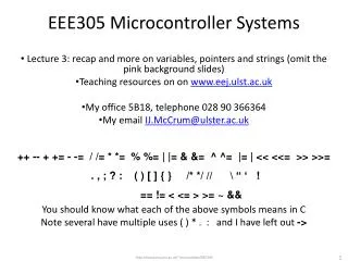
Part 1 MICROCONTROLLER SYSTEMS
Input Peripherals CPU Central Processing Unit Output Peripherals User input User output ROM Read Only Memory RAM Read & Write Memory Program download Figure 1.1 Elements of a digital controller The microcontroller contains all these elements in one chip
Figure 1.2 16F877 pin-out The microcontroller pins have multiple functions
Flash ROM Program Memory 8192 x 14 bits 0000 – 1FFF Program Counter (13 bits) Address RAM File Registers 368 X 8 bits 000-1FF Stack 13 bits x 8 levels Instructions Instruction Register File Address Program address Working (W) Register File Select Register Literal Arithmetic & Logic Unit Status bits Status (Flag) Register Op-code Data Bus (8 bits) EEPROM 256 bytes Instruction Decode & CPU control MCU control lines Ports, Timers ADC, Serial I/O Timing control Clock Reset Port A B C D E Figure 1.3 PIC 16F877 MCU Block diagram Shows the main parts of the chip in simplified form
Bank 0 (000 – 07F) Bank 1 (080 – 0FF) Bank 2 (100-180) Bank 3(180-1FF) Address Register Address Register Address Register Address Register 000h Indirect 080h Indirect 100h Indirect 180h Indirect 001h Timer0 081h Option 101h Timer0 181h Option 002h PC Low 082h PC Low 102h PC Low 182h PC Low 003h Status Reg 083h Status Reg 103h Status Reg 183h Status Reg 004h File Select 084h File Select 104h File Select 184h File Select 005h Port A data 085h PortA direction 105h - 185h - 006h Port B data 086h PortB direction 106h Port B data 186h PortB direction 007h Port C data 087h PortC direction 107h - 187h - 008h Port D data 088h PortD direction 108h - 188h - 009h Port E data 089h PortE direction 109h - 189h - 00Ah PC High 08Ah PC High 10Ah PC High 18Ah PC High 00Bh Interrupt Control 08Bh Interrupt Control 10Bh Interrupt Control 18Bh Interrupt Control 00Ch to 01Fh 20 Peripheral Control Registers 08Ch to 09Fh 20 Peripheral Control Registers 10Ch to 10Fh 4 Peripheral Control Registers 18Ch to 18Fh 4 Peripheral Control Registers 110h to 16Fh 96 General Purpose Registers 190h to 1EFh 96 General Purpose Registers 020h to 06Fh 80 General Purpose Registers 0A0h to 0EFh 80 General Purpose Registers 070h to 07Fh 16 Common Access GPRs 0F0h to 0FFh Accesses 70h – 7Fh 170h to 17Fh Accesses 70h – 7Fh 1F0h to 1FFh Accesses 70h – 7Fh Table 1.1 PIC16F877 simplified file register map
MCU Pins Data word (bits) Program memory (bytes) Typical Instruction Set Speed MIPS Comment 10FXXX = 6 8 <= 512 33 x 12 bits <= 2 Low pin count, small form factor, cheap No EEPROM, none low power, assembler program 12FXXX = 8 8 <= 2 KB 12 / 14 bits <= 5 Low pin count, small form factor, cheap EEPROM, 10-bit ADC, some low power, assembler 16FXXX <= 64 8 <= 14 KB 35 x 14 bits <= 5 Mid-range, UART, I2C, SPI many low power, C or assembler program 18FXXXX <= 100 8 <= 128 KB 75 x 16 bits <= 16 High range, CAN, USB J series 3V supply, C program 24FXXXX <= 100 16 <= 128 KB 76 x 24 bits = 16 Power range, 3V supply, no EEPROM, data RAM < 8 KB, C program Table 1.2 PIC microcontroller types
Data Direction Latch Write TRIS bit Tri-state Output Enable Output Data Latch Output Current Driver CPU Data Bus Write data bit Input Data Latch Read data bit Analogue input multiplexer Figure 1.4 I/O pin operation The pin can be set for input or output data transfer
Capture signal Capture register Timer Overflow/ Timeout (Interrupt) Flag Instruction Clock Clock Source Select Pre-scaler (clock divide) Post-scaler (output divide) Binary Counter External Pulse Compare register Match flag Figure 1.5 General Timer Operation A binary counter is used as a timer when driven from the clock
Input volts 0-Vf ANx Analogue to Digital Converter Vref+ Setup ADC Read ADC 8-bit or 16-bit integer result Reference volts, Vf Figure 1.6 ADC operation The ADC converts an analog input into a binary code
Vc+ Vc- Compartor status bit Vc+ > Vc- Figure 1.7 Comparator operation The comparator simply sets a bit if one input is higher than the other
Chip select Read Write EXTERNAL Data x 8 Parallel Slave Port Interrupt INTERNAL Data x 8 Figure 1.8 Parallel Slave Port operation The PSP allows an external data bus to be connected to the MCU
Interrupt Source Interrupt trigger event CCS C Interrupt label TIMERS Timer 0 Timer 0 register overflow INT_TIMER0 Timer 1 Timer 1 register overflow INT_TIMER1 CCP 1 Timer 1 capture or compare detected INT_CCP1 Timer 2 Timer 2 register overflow INT_TIMER2 CCP2 Timer 2 capture or compare detected INT_CCP2 PORTS RB0/INT pin Change on single pin RB0 INT_EXT Port B pins Change on any of four pins RB4 – RB7 INT_RB Parallel Slave Port Data received at PSP (write input active) INT_PSP Analog Converter A/D conversion completed INT_AD Analog Comparator Voltage compare true INT_COMP SERIAL UART Serial Port Received data available INT_RDA UART Serial Port Transmit data buffer empty INT_TBE SPI Serial Port Data transfer completed (read or write) INT_SSP I2C Serial Port Interface activity detected INT_SSP I2C Serial Port Bus collision detected INT_BUSCOL MEMORY EEPROM Non-volatile data memory write complete INT_EEPROM Table 1.3 Interrupts sources in the PIC 16F877
Program Execution Program Execution 1 Start counter statement 2 Run Counter until overflow 3 Timeout Interrupt 7 Continue 5 Time-out Process (Interrupt Service Routine) 6 Return from Interrupt Figure 1.9 Timer Interrupt Process 4 Jump to ISR Time-out forces the program to be suspended and the ISR executed
HOST PC RX2 TX2 COM PORT Ground PIC MCU TX1 Transmit RX1 Receive Ground Line Driver Interface Figure 1.10 USART RS232 Signal +/- 12V Line drivers convert the signal to a bipolar, higher voltage
Bit period 1 0 Time Idle Start Bit Bit 0 Bit 1 Bit 2 Bit 3 Bit 4 Bit 5 Bit 6 Bit 7 Stop Bit Figure 1.11 Typical USART RS232 signal The data bits are timed from the falling edge of the start bit
Master Serial Data Out, SDO Serial Data In, SDI Serial Clock, SCK Slave Select SS1 Outputs SS2 SS3 Slave 1 SDO SDI SCK !SS Slave 2 SDO SDI SCK !SS Figure 1.12 SPI Connections SPI uses hardware slave selection and separate clock
Figure 1.13 SPI Signals SDO/SDI 7 6 5 4 3 2 1 0 Data bits SCK Clock Each data bit is transferred on the falling edge of the clock
Figure 1.14 I2C Connections +5V Master Slave1 Slave2 etc SDA SCL Slave selection uses addresses issued by the Master
Figure 1.15 I2C Signals Start Acknowledge Address / Data bits SDA 7 6 5 4 3 2 1 0 SCL Data is strobed in using the master clock, and reception is acknowledged by the slave by taking the data line low
Listing 1.1 A simple C program /* OUTBYTE.C MPB 2-1-07 V1.0 */ #include "16F877A.h" // MCU select void main() // Main block { output_D(255); // Switch on outputs } This minimal program outputs a binary code to Port D
Listing 1.2 Program hex file :1000000000308A0004280000840183131F30830518 :1000100083161F149F141F159F1107309C00880121 :08002000FF3083128800630029 :02400E00733FFE :00000001FF ;PIC16F877A The machine code is downloaded as a binary file to the chip
Figure 1.16 Screenshot of MPLAB Project The C program is compiled and tested in simulation mode
Application Board Reset MCU Vpp/!MCLR Vdd Vss PGD PGC 10k 1 2 3 4 5 ICSP Interface Vdd Vss Board +5V Supply Figure 1.17 ICSP target board connections Connections to the target chip for programming