Download
1 / 13

E N D
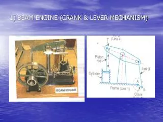
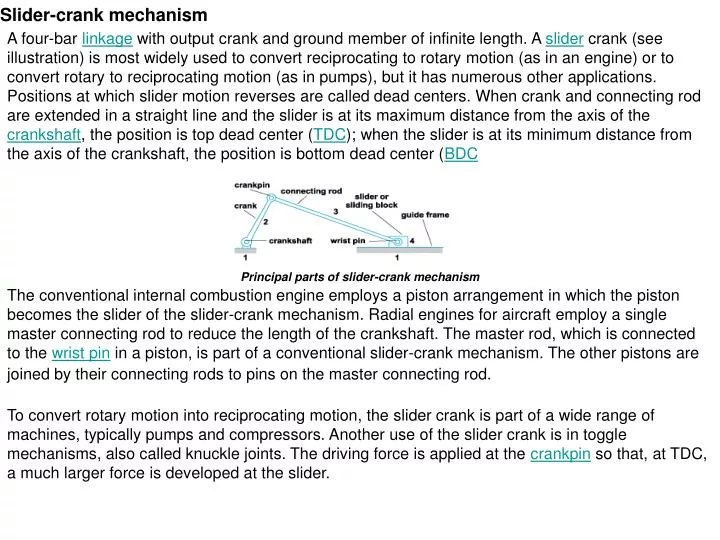
Slider-crank mechanism A four-bar linkage with output crank and ground member of infinite length. A slider crank (see illustration) is most widely used to convert reciprocating to rotary motion (as in an engine) or to convert rotary to reciprocating motion (as in pumps), but it has numerous other applications. Positions at which slider motion reverses are called dead centers. When crank and connecting rod are extended in a straight line and the slider is at its maximum distance from the axis of the crankshaft, the position is top dead center (TDC); when the slider is at its minimum distance from the axis of the crankshaft, the position is bottom dead center (BDC Principal parts of slider-crank mechanism The conventional internal combustion engine employs a piston arrangement in which the piston becomes the slider of the slider-crank mechanism. Radial engines for aircraft employ a single master connecting rod to reduce the length of the crankshaft. The master rod, which is connected to the wrist pin in a piston, is part of a conventional slider-crank mechanism. The other pistons are joined by their connecting rods to pins on the master connecting rod. To convert rotary motion into reciprocating motion, the slider crank is part of a wide range of machines, typically pumps and compressors. Another use of the slider crank is in toggle mechanisms, also called knuckle joints. The driving force is applied at the crankpin so that, at TDC, a much larger force is developed at the slider.
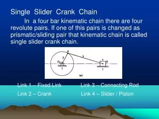
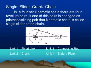
Linkage (mechanism):A set of rigid bodies, called links, joined together at pivots by means of pins or equivalent devices. A body is considered to be rigid if, for practical purposes, the distances between points on the body do not change. Linkages are used to transmit power and information. They may be employed to make a point on the linkage follow a prescribed curve, regardless of the input motions to the linkage. They are also used to produce angular or linear displacement. If the links are bars the linkage is termed a bar linkage. A common form of bar linkage is one for which the bars are restricted to a given plane, such as a four-bar linkage. A commonly occurring variation of the four-bar linkage is the linkage used in reciprocating engines (see illustration). Slider C is the piston in a cylinder, link 3 is the connecting rod, and link 4 is the crank. (Link 1 is the fixed base, A and D are pivots, R is the length of the crank, L is the length of the connecting rod, and τ denotes the angle of the crank.) This mechanism transforms a linear into a circular motion, or vice versa. The straight slider in line with the crank center is equivalent to a pivot at the end of an infinitely long link. Crank angle: The angle between a crank and some reference direction. Specifically, the angle between the crank of a slider crank mechanism and a line from crankshaft to the piston. connecting rod: A rod that transmits motion or power from one moving part to another, especially the rod connecting the crankshaft of a motor vehicle to a piston. Also called pitman.
Crankshaft geometry: Definitions l = rod length (distance between piston pin and crank pin)r = crankradius (distance between crank pin and crank center, i.e. half stroke)A = crank angle (from cylinderbore centerline at TDC)x= piston pin position (upward from crank center along cylinder bore centerline)v = piston pin velocity (upward from crank center along cylinder bore centerline)a = piston pin acceleration (upward from crank center along cylinder bore centerline)ω = crank angular velocity in rad/s Diagram showing geometric layout of piston pin, crank pin and crank center
Angular velocity: The crankshaftangular velocity is related to the engine revolutions per minute (RPM): Triangle relation: As shown in the diagram, the crank pin, crank center and piston pin form triangle NOP.By the cosine law it is seen that: Equations with respect to angular position (Angle Domain): The equations that follow describe the reciprocating motion of the piston with respect to crank angle.Example graphs of these equations are shown below. Position: Position with respect to crank angle (by rearranging the triangle relation):
Velocity: Velocity with respect to crank angle (take first derivative, using the chain rule): Acceleration: Acceleration with respect to crank angle (take second derivative, using the chain rule and the quotient rule):
Example graph of piston motion: The graph shows x, x', x" wrt to crank angle for various half strokes, where L = rod length (l) and R = half stroke (r): The vertical axis units are inches for position, [inches/rad] for velocity, [inches/rad²] for acceleration.The horizontal axis units are crank angle degrees.
Experiment # 1: Slider crank mechanism Learning Objectives / Experiments: - Crank drive with fixed cylinder - Crank drive with swivelling cylinder Exp. Procedure and Readings to be taken: 1- select and adjust certain r and L. 2- calculate the ratio: λ = r / L 3- measure the piston displacement (x) and plot graph (x) against the crank angle (θc).
4- The piston traveling stroke: range: Xmax – Xmin =______________________________________ 5- graph the function 6- graph differentiating piston displacement (V) versus crank angle (θ)
Experiment # 2: Four bar mechanism A four bar linkage or simply a 4-bar or four-bar is the simplest movable linkage. It consists of 4 rigid bodies (called bars or links), each attached to two others by single joints or pivots to form a closed loop. The plane four-bar linkage (Fig. 1) consists of four pin-connected links forming a closed loop, in which all pin axes are parallel. The spherical four-bar linkage consists of four pin-connected links forming a closed loop, in which all pin axes intersect at one point. The skew four-bar linkage (Fig. 2) consists of four jointed links forming a closed loop, in which crank 2 and link 4 are pin-connected to ground 1 and the axes of the pins are generally nonparallel and nonintersecting; coupler 3 is connected to crank 2 and link 4 by ball joints. Plane four-bar linkage with joints at A, B, C, and D. φ, ψ, and μ are angles defining orientations of joints. Four-bar linkages are most frequently used to convert a uniform continuous rotation (the motion of crank 2) into a nonuniform rotation or oscillation (the motion of link 4). In instrument applications the primary function of the linkage is the conversion of motion, while in power applications both motion conversion and power transmission are fundamental.
Learning Objectives / Experiments: - Investigation of the mechanical relationships on four bar chain mechanisms- Checking the Grashof set by varying the crank radius, radius of oscillation and connecting rod length Exp. Procedure and Readings to be taken: 1- Select and adjust two sets of values. State 1:_____________________________________ State 2:_____________________________________ 2- Verifying that selection satisfies Garshof law for the both states. Where: s + ℓ ≤ p + q 3- Measure the output angle with a crank-and-rocker linkage and plot the graph for both states that have been chosen by you. 4- Calculate the driven crank traveling stroke in: state 1: the driven crank traveling stroke = θc(max) – θc(min) =_________________ state 2: the driven crank traveling stroke = θc(max) – θc(min) =_________________
Experiment # 3: Quick Return mechanism The Whitworth quick return mechanism converts rotary motion into reciprocating motion, but unlike the crank and slider, the forward reciprocating motion is at a different rate than the backward stroke. At the bottom of the drive arm, the peg only has to move through a few degrees to sweep the arm from left to right, but it takes the remainder of the revolution to bring the arm back. This mechanism is most commonly seen as the drive for a shaping machine. Learning Objectives / Experiments: - Output stroke of Whitworth's quick return as a function of the input angle of the drive crank Exp. Procedure and Readings to be taken: 1- select and adjust certain r and L 2- measure the piston displacement (x) and plot graph (x) against the crank angle (θ) 3- the piston traveling stroke: Range = Xmax – Xmin =__________________________________
Note: after you accomplish your report and all its items (introduction, theoretical basis and back ground, description of test rig, measurement and results, discussion and conclusion, and appendix). Now it is time to write your conclusion. The conclusion, plain and simple, is the answer to your question. It should be clear, conciseand stick to the point. Resist the temptation to jump to conclusions. If you were to do your experiment again, would you get the same results? Can there be differences? Why? Ask yourself what happened when you tested your hypothesis. What have you learned? Write a final report summarizing your question, research methods and conclusion.