Download
1 / 167
1.67k likes | 1.91k Views
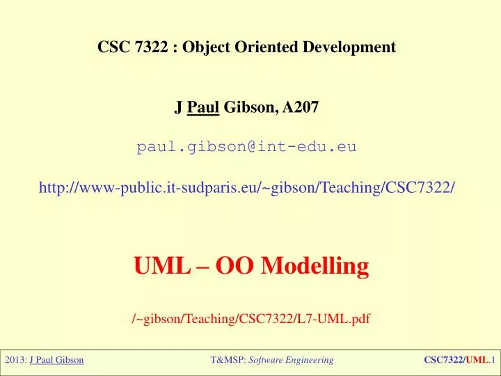
CSC 7322 : Object Oriented Development J Paul Gibson, A207 paul.gibson@int-edu.eu http://www-public. it-sudparis.eu /~gibson/Teaching/CSC7322/. UML – OO Modelling /~gibson/Teaching/CSC7322/L7-UML.pdf. UML - Introduction. Overview: Edited From Wikipedia, the free encyclopedia

E N D
CSC 7322 : Object Oriented Development J Paul Gibson, A207 paul.gibson@int-edu.eu http://www-public.it-sudparis.eu/~gibson/Teaching/CSC7322/ UML – OO Modelling /~gibson/Teaching/CSC7322/L7-UML.pdf T&MSP: Software Engineering
UML - Introduction T&MSP: Software Engineering
Overview: Edited From Wikipedia, the free encyclopedia The Unified Modeling Language (UML) is a standardized specification language for object modeling. UML is a general-purpose modeling language that includes a graphical notation used to create an abstract model of a system, referred to as a UML model. UML is officially defined at the Object Management Group (OMG) by the UML metamodel, a Meta-Object Facility metamodel (MOF). UML was designed to specify, visualize, construct, and document software-intensive systems. UML is not restricted to modeling software. UML is also used for business process modeling, systems engineering modeling, and representing organizational structures. T&MSP: Software Engineering
Overview: Edited From Wikipedia, the free encyclopedia The Systems Modeling Language (SysML) is a Domain-Specific Modeling language for systems engineering that is defined as a UML 2.0 profile. UML has been a catalyst for the evolution of model-driven technologies, which include Model Driven Development (MDD), Model Driven Engineering (MDE), and Model Driven Architecture (MDA). By establishing an industry consensus on a graphic notation to represent common concepts like classes, components, generalization, aggregation, and behaviors, UML has allowed software developers to concentrate more on design and architecture. UML models may be automatically transformed to other representations (e.g. Java) by means of transformation languages, supported by the OMG. UML is extensible, offering the following mechanisms for customization: profiles and stereotype. The semantics of extension by profiles has been improved with the UML 2.0 major revision. T&MSP: Software Engineering
UML Founding Fathers: The three amigos • James Rumbaugh: OMT – ‘best’ for OOA • James Rumbaugh, Michael Blaha, William Premerlani, Frederick Eddy, William Lorensen: Object-Oriented Modeling and Design, Prentice Hall, ISBN 0-13-629841-9 • Grady Booch: Booch method – ‘best’ for OOD • (1993). Object-oriented Analysis and Design with Applications, 2nd ed., Redwood City: Benjamin Cummings. ISBN 0-8053-5340-2. • Ivar Jacobson: OOSE method - first object-oriented design methodology to employ use cases. • Object-Oriented Software Engineering: A Use Case Driven Approach, Addison-Wesley Professional (1992). ISBN 0201544350 T&MSP: Software Engineering
UML Founding Fathers: The three amigos Rational Machines was founded by Paul Levy and Mike Devlin in 1981 to provide tools to expand the use of modern software engineering practices, particularly explicit modular architecture and iterative development. Grady Booch was a chief scientist at Rational, working on graphical notations Rational Software Corporation hired James Rumbaugh from General Electric in 1994, the company became the source for the two most popular object-oriented modeling approaches of the day (OMT and Booch Method) Together Rumbaugh and Booch attempted to reconcile their two approaches and started work on a Unified Method. Joined by Ivar Jacobson, the creator of the OOSE method, in 1995, after his company, Objectory, was acquired by Rational. The three methodologists were collectively referred to as the Three Amigos, since they were well known to argue frequently with each other regarding methodological preferences. (Jacobson: "What's the difference between a terrorist and a methodologist? You can negotiate with a terrorist".) Rational was sold for $2.1B to IBM on February 20, 2003 T&MSP: Software Engineering
Development History Under the technical leadership of the Three Amigos, an international consortium called the UML Partners was organized in 1996 to complete the Unified Modeling Language (UML) specification, and propose it as a response to the OMG RFP. The UML Partners' UML 1.0 specification draft was proposed to the OMG in January 1997. During the same month the UML Partners formed a Semantics Task Force, chaired by Cris Kobryn and administered by Ed Eykholt, to finalize the semantics of the specification and integrate it with other standardization efforts. The result of this work, UML 1.1, was submitted to the OMG in August 1997 and adopted by the OMG in November 1997. T&MSP: Software Engineering
Development History As a modeling notation, the influence of the OMT notation dominates (e.g., using rectangles for classes and objects). Though the Booch "cloud" notation was dropped, the Booch capability to specify lower-level design detail was embraced. The use case notation from Objectory and the component notation from Booch were integrated with the rest of the notation, but the semantic integration was relatively weak in UML 1.1 This was not really fixed until the UML 2.0 major revision. T&MSP: Software Engineering
Development History • The Unified Modeling Language is an international standard: • ISO/IEC19501:2005 Information technology -- Open Distributed Processing -- Unified Modeling Language (UML) Version 1.4.2. • UML has matured significantly since UML 1.1. Several minor revisions (UML 1.3, 1.4, and 1.5) fixed shortcomings and bugs with the first version of UML, followed by the UML 2.0 major revision, which is the current OMG standard. T&MSP: Software Engineering
Development History The first part of UML 2.0, the Superstructure which describes the new diagrams and modeling elements available, was adopted by the OMG in October 2004. Other parts of UML 2, notably the infrastructure, the Object Constraint Language (OCL) and the diagram interchange were ratified later. The final UML 2.0 specification has been declared available and has been added to OMG's formal specification library. The other parts of the UML specification, the UML 2.0 infrastructure, the UML 2.0 Diagram Interchange, and UML 2.0 OCL specifications have been adopted. UML version 2.1 revision is being developed, and should be available in the form of an XMI 2.1 version of the UML 2.1 version. The corresponding XMI 2.1 file will be made available from the OMG ADTF group. Most of the commercially successful UML tools now support most of UML 2.0 T&MSP: Software Engineering
Modeling • It is very important to distinguish between the UML model and the set of diagrams of a system. • A diagram is a partial graphical representation of a system's model. The model also contains a "semantic backplane" — documentation such as written use cases that drive the model elements and diagrams. • There are three prominent parts of a system's model: • Functional Model • Showcases the functionality of the system from the user's Point of View. • Includes Use case diagrams. • Object Model • Showcases the structure and substructure of the system using objects, attributes, operations, and relationships. • Includes Class Diagrams. • Dynamic Model • Showcases the internal behavior of the system. • Includes sequence diagrams, activity diagrams and state machine diagrams. • Models can be exchanged among UML tools by using the XMI (XML Metadata Interchange) format. T&MSP: Software Engineering
UML Diagrams In UML 2.0 there are 13 types of diagrams. To understand them, it is sometimes useful to categorize them hierarchically: Structure Diagrams emphasize what things must be in the system being modeled: * Class diagram * Component diagram * Composite structure diagram * Deployment diagram * Object diagram * Package diagram T&MSP: Software Engineering
UML Diagrams continued … Behavior Diagrams emphasize what must happen in the system being modeled: * Activity diagram * State Machine diagram * Use case diagram Interaction Diagrams, a subset of behavior diagrams, emphasize the flow of control and data among the things in the system being modeled: * Communication diagram * Interaction overview diagram (UML 2.0) * Sequence diagram * UML Timing Diagram (UML 2.0) T&MSP: Software Engineering
A (UML Class) Diagram of the 3 main categories of UML diagram T&MSP: Software Engineering
UML Diagrams: Learning Priorities Typical Depending on what you need/want to learn T&MSP: Software Engineering
Criticisms • Although UML is a widely recognized and used modeling standard, it is frequently criticized for the following deficiencies - • Language bloat: UML is often criticized as being gratuitously large and complex. • Imprecise semantics: Since UML is specified by a combination of itself (abstract syntax), OCL (well-formedness rules) and English (detailed semantic), it lacks the rigor of a language precisely defined using formal language techniques. • Problems in learning and adopting: Language bloat and imprecise semantics make learning and adopting UML problematic, especially when management forces UML upon engineers lacking the prerequisite skills. • Only the code is in sync with the code: UML has value in approaches that compile the models to generate code. This however, may still not be sufficient since UML as a language does not exhibit Turing completeness, and any generated source or executable code would be limited to what a UML interpreting tool can discern or assume. • Cumulative Impedance/Impedance mismatch: As with any notational system, UML is able to represent some systems more concisely or efficiently than others. • Tries to be all things to all people: UML is a general purpose modeling language, which tries to achieve compatibility with every possible implementation language. T&MSP: Software Engineering
Introducing Notation: Object Diagrams Unsurprisingly, as the basic currency of object orientation is objects, we can use UML to describe objects, their attributes - the facts that we can know about them - and the relationships between objects at some point in time. T&MSP: Software Engineering
Introducing Notation: Object Diagrams More formally in UML: T&MSP: Software Engineering
Introducing Notation: Object Diagrams It is important to note that objects have a unique identity that remains unchanged throughout their lifetimes. Ellie Foster is still the same person, even after she has changed her name to Ellie Green. Another important thing to note about objects is that they can play different roles in respect of each other. They can play more than one role at the same time. For example, Ellie Foster is a wife to Tom Green, a mother to Tom Green Jr and the author of Real Fast Food. As well as describing objects, we can use UML to model types of objects, that is, sets of similar objects that share the same characteristics. Types, or classes, as they are more commonly known in object oriented software development, tell us what attribute values any instance of that type is allowed to have, what roles objects of that type are allowed to play, and how many objects are allowed to play the same role with respect to the same object. We use the term multiplicity to refer to the number of objects that are allowed to play the same role at the same time with respect to another object. For example, in the relationship mother->son, the role of son can be played by zero or more objects of type Man at the same time with respect to the same Woman, so the multiplicity of the role son is zero or more (or 0..*, or just *, in UML). In the reverse, only one Woman can play the role of mother with respect to the same Man, so the multiplicity of the role mother is exactly one (or simply 1 in UML). T&MSP: Software Engineering
Introducing Notation: Object Diagrams Multiplicity (informally): T&MSP: Software Engineering
The relationship between objects and types (or classes). An object is said to be an instance of a type - a specific example of that type. Every instance of a type has the characteristics defined by that type, and must obey any rules that apply to it. If our type model tells us that every Man has exactly one mother, for example, then an object of type Man with no mother, or with two mothers, does not conform to its type. So a type, or class, model tells us the rules about what instances of objects, their attributes and the relationships between them are allowed. But quite often they do not tell us all of the rules. Sometimes rules about types can be more complex and subtle than, eg, a Man must have exactly one mother. For example, how can we model the fact that a Woman cannot have a son who is also the father of any of her other sons? We can use object models to illustrate scenarios that might break these subtle rules. T&MSP: Software Engineering
The relationship between objects and types (or classes). Ellie Foster cannot be the mother of Tom Green because he is the father of her son, Tom Green Jr. This can be added to the model as a rule (or constraint): { son cannot be father of any other sons } T&MSP: Software Engineering
More formal class diagrams using OCR? We can also combine UML with more formal models (in Event-B, eg) T&MSP: Software Engineering
Modelling Behaviour State transition models allow us to model object lifecycles and event-driven behaviour T&MSP: Software Engineering
Modelling Behaviour: adding constraints We can use constraints that apply to transitions to show how a certain event triggers a certain transition from one state to another only when some condition is true. For example, when the publisher reviews the draft of a book in development, it could take the book into production design, but only if the publisher has approved the draft. We call constraints on transitions guard conditions. In UML, guard conditions are written in square brackets after the event. Optionally, we can also show how some action is executed as a result of a transition, eg: we might want to show that the designer should revise his design for a book if his last design was not approved when the publisher reviewed it. Actions appear after that event and the guard - if there is one - for a transition. T&MSP: Software Engineering
Modelling interactions with sequence diagrams T&MSP: Software Engineering
Modelling interactions with sequence diagrams Once we have identified the objects involved and their relationships, we must now decide which object is taking responsibility for what action in the execution of a process. Sequence models describe how objects send messages to each other - through well- defined interfaces - asking them to do some useful piece of work. Each type of object has responsibility for providing a set of services, and the interface for each type public face through which other objects can request those services. In UML, we call those services operations. A sequence model shows how, over time - and for a specific scenario (a specific instance of a process - or a pathway through that process): the objects involved use each others’ operations to get the job done. Assigning these responsibilities is a key part in the object oriented thought design process, and we will see how these models can be used in a well-defined and rigorous object oriented development process. T&MSP: Software Engineering
Modelling interactions with sequence diagrams Objects, like an author, can be found in many different interaction diagrams: T&MSP: Software Engineering
Use case diagrams: special type of sequence diagram? Use case diagrams show the different classes of user and the goals they can achieve using the system Some software development processes are said to be use case-driven, in so much as they are driven by requirements T&MSP: Software Engineering
Example Activity Diagram An activity diagram models the flow of actions in some process or workflow. It could be a business process, or it could be the control flow of program code. An activity diagram shows sequences of activity states - or actions -where when one action is complete the flow immediately moves on to the next action. This automatic transitioning from one activity state to the next is what distinguishes activity diagrams from state transition diagrams. T&MSP: Software Engineering
Example Activity Diagram Start state T&MSP: Software Engineering
Why not use a state transition diagram? T&MSP: Software Engineering
… Or a collaboration diagram? Or ... Etc …? T&MSP: Software Engineering
When modelling becomes questionable: component diagrams UML has special notations for representing physical components, their interfaces, thedependencies between them, and their deployment architectures. Its worth nothing,though, that at this low level of abstraction the benefits of modeling start to become questionable. T&MSP: Software Engineering
When modelling becomes questionable: packages Packages & Model Management Just as we can group files on our computers into folders to make them easier to find,we can break large models down into packages that group related model elements together. T&MSP: Software Engineering
Learning UML: different, complementary approaches • By memorising: • Diagram by Diagram • By analysing: • Case Studies • By doing: • OO Analysis, Requirements and Design • By having large scale problems: • Software Engineering Process – co-ordinating diagrams • By using tools: • Validation, Verification, Code Generation, Reverse Engineering T&MSP: Software Engineering
Does UML meet your needs? • What requirements do you have of your modeling language? • What sort of things should it be able to represent elegantly? • Repeat • Think about a problem/case study/project that you have done • What sort of things were you reasoning about? • What sort of notation did you use? • Until you think you have a complete understanding of these things • How do you do these in Event-B (if at all)? T&MSP: Software Engineering
Does UML meet your/our needs? Extending the UML Sometimes it is necessary to convey more information than vanilla UML is able to describe. We have already seen one mechanism for adding extra information to our models - using constraints. The UML standard provides two other mechanisms for extending the language: stereotypes and tagged values. T&MSP: Software Engineering
Additional Reading Material • UML3.0 and the future of modeling, Cris Kobryn, 2004 • DeathBy UML Fever, Alex E Bell, 2004 • UML Fever: Diagnosis and Recovery, Alex E Bell, 2005 • The UML as a FormlModeling Notation, France, Evans, Lano and Rump, 1998 • On formalizing the UML objectconstraintlanguage OCL, Mark Richters and Martin Gogolla, 1998 • TeachingUML isTeaching Software Engineering isTeaching Abstraction, Gregor Engels, Jan Hendrik Hausmann, Marc Lohmann, Stefan Sauer, 2005 T&MSP: Software Engineering
Useful Resources MyLittle UML (Tools) Page: Michael W. Godfrey's pointers to usefultools Violet UML Editor: standalone editor with minimal functionality (multi-platform, jre) ArgoUML : Eclipse Plugin (or standaloneapp) ArgoUMLreferencemanual Fujaba4Eclipse: From UML to Java and back again (Eclipse plugin) TopCased:Open Source Toolkit for criticalsystems TO DO: Email me links/detailsconcerning the UML toolsthatyoucurrently use (or have used) T&MSP: Software Engineering
SOME UML NOTATION T&MSP: Software Engineering
Class Diagrams A Class defines the attributes and the methods of a set of objects. All objects of this class (instances of this class) share the same behaviour, and have the same set of attributes (each object has its own set). The term “Type” is sometimes used instead of Class, but it is important to mention that these two are not the same, and Type is a more general term. In UML, Classes are represented by rectangles, with the name of the class, and can also show the attributes and operations of the class in two other “compartments” inside the rectangle. T&MSP: Software Engineering
Class Diagrams Graphical Notation, example: T&MSP: Software Engineering
Class Diagrams Attributes In UML, Attributes are shown with at least their name, and can also show their type, initial value and other properties. Attributes can also be displayed with their visibility: + public attributes # protected attributes - private attributes T&MSP: Software Engineering
Class Diagrams Operations Operations (methods) are also displayed with at least their name, and can also show their parameters and return types. Operations can, just as Attributes, display their visibility: + public operations # protected operations - private operations T&MSP: Software Engineering
Class Diagrams Templates Classes can have templates, a value which is used for an unspecified class or type. The template type is specified when a class is initiated (i.e. an object is created). Templates exist in C++ and were introduced in Java 1.5 where they are also called Generics. T&MSP: Software Engineering
Class Relations Generalisation Inheritance is one of the fundamental concepts of Object Orientated programming, in which a class “gains” all of the attributes and operations of the class it inherits from, and can override/modify some of them, as well as add more attributes and operations of its own. In UML, a Generalisation association between two classes puts them in a hierarchy representing the concept of inheritance of a derived class from a base class. In UML, Generalisations are represented by a line connecting the two classes, with an arrow on the side of the base class. T&MSP: Software Engineering
Class Relations Interface – implementing (a contract) In the diagram both the Professor and Student classes implement the Person interface and do not inherit from it. We know this for two reasons: 1) The Person object is defined as an interface — it has the "«interface»" text in the object's name area, and we see that the Professor and Student objects are class objects because they are labeled according to the rules for drawing a class object (there is no additional classification text in their name area). 2) We know inheritance is not being shown here, because the line with the arrow is dotted and not solid. T&MSP: Software Engineering
Class Relations Associations An association represents a relationship between classes, and gives the common semantics and structure for many types of “connections” between objects. Associations are the mechanism that allows objects to communicate to each other. It describes the connection between different classes (the connection between the actual objects is called object connection, or link.) Associations can have a role that specifies the purpose of the association and can be uni- or bidirectional (indicates if the two objects participating in the relationship can send messages to the other, of if only one of them knows about the other). Each end of the association also has a multiplicity value, which dictates how many objects on this side of the association can relate to one object on the other side. T&MSP: Software Engineering
Class Relations Associations In UML, associations are represented as lines connecting the classes participating in the relationship, and may also show the role and the multiplicity of each of the participants. Multiplicity is displayed as a range [min..max] of non-negative values, with a star (*) on the maximum side representing infinite. T&MSP: Software Engineering