Download
1 / 25
250 likes | 257 Views
Optical links in the 25ns test beam. Karl Gill CERN Acknowledgements: O-link and MIC teams. CMS Tracker readout and control links. Final system. Analogue Readout 50000 links @ 40MS/s. FED. Detector Hybrid. Tx Hybrid. 96. Rx Hybrid. processing. MUX. A. buffering. APV. 4. DAQ.

E N D
Optical links in the 25ns test beam Karl Gill CERN Acknowledgements: O-link and MIC teams
CMS Tracker readout and control links • Final system Analogue Readout 50000 links @ 40MS/s FED Detector Hybrid Tx Hybrid 96 Rx Hybrid processing MUX A buffering APV 4 DAQ 2:1 D amplifiers 12 12 C pipelines 128:1 MUX PLL Delay Timing DCU TTCRx TTC Digital Control 2000 links @40MHz FEC Control 64 4 TTCRx CCU CCU 8 processing buffering CCU CCU Back-End Front-End
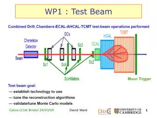
X5 system test setup • In the beam area: • 4 modules, each including: • Si detector • 4 APV6 chips • CCU card • TRI card • analogue optical link • timing/control ring • digital links to/from control ring
X5 analogue o-links - transmitter • 4-channel laser package • 4-channel analogue laser driver chip • 4-ch transmitter daughter card 4-way laser package
X5 analogue o-links - fibre • single mode optical fibre: • 4-way ribbon pigtails at Tx, Rx • 12-way fibres ribbons • with 12 way MT connectors • using only the 4 central fibres • 96 fibre cable • 8x12 ribbons 96-way cable and 12-way optical ribbon and MT-connector
X5 analogue Links - receiver • Receiver side: • optical ribbon connectors • 4x 4-way receiver card • jumper cables to FED input 4-way receiver daughter-board
X5 digital links • 2 x 2-way transmitter and receiver • one unit located next to FEC, another inside beam area
CMS Tracker readout and control links • Final system Analogue Readout 50000 links @ 40MS/s FED Detector Hybrid Tx Hybrid 96 Rx Hybrid processing MUX A buffering APV 4 DAQ 2:1 D amplifiers 12 12 C pipelines 128:1 MUX PLL Delay Timing DCU TTCRx TTC Digital Control 2000 links @40MHz FEC Control 64 4 TTCRx CCU CCU 8 processing buffering CCU CCU Back-End Front-End
Analogue readout chain (without optical link) • TRI-card to FED (e.g. with copper link) from APV • APV output 50mA per MIP • 120mV into FED per MIP (for link gain = 1) • +/- 750mV FED input range equivalent to 12.5MIP
Analogue optical link • Each component contributes a gain factor: fibre/connectors laser photodiode receiver laser driver • Expect spread of optical link gain (2.5-4.0 overall): • losses at optical connections • variation of laser, receiver efficiency • Will have programmable gain compensation in final links
Nominal Optical vs Cu link gain Vin at FED (mV) Go-link =2.5-4.0 1500 GCu-link=1 1000 500 0 0 2 4 6 8 10 12 signal (MIPs) • Limited dynamic range (~4MIPs) for nominal o-link gain • Note, in final system Go-link will be ~1
Link gain attenuation • Potential divider added to attenuate input to link • Different values of R tried in X5 • R=27W (A=21%), 91W (A=48%), 200W (A=66%) • test effect of spread in gain on system • noise penalty with large gain in optical link
Full chain • Schematic of full analogue readout chain current offset attenuation laser dc bias Receiver output offset • link integration: • connection then setting of gains and offsets • setup/calibration should be made automatic in future • 16 (+4) readout channels instrumented in total
Gain + offset settings from TRI to FED • e.g. for R=91W adjustable TRI dc baseline Tick 210mV -600 -300 0 +300 +600 Vout (TRI) Tick 105mV X 0.50(adjustabledivider, R=91W ) Vin (O-link) -400 +400 adjustable laser dc bias-point X 3.0 (link-average) Vout (O-link) -1200 +1200 Tick 315mV Vin (FED) adjustable receiver output dc offset +750 -750 FED output 0 256 512 Tick 110 counts Offset + gain settings should be automated in future
APV analogue biaspoint Vin FED (mV) 1500 overall ± n MIPs dynamic range digital header + pipeline addr. 1000 VADJ 500 tick analogue data 0 Time (a.u.) • Vadj at APVs set to correspond to 0V into FED • 0V was ~256 ADC counts
Measured gain: link + divider • based on tick marks at TRI and receiver outputs No 3rd gain setting for CCU12, 14 • O-link gain remains fixed at ~3, series resistor values at input changed
Lab measurement (gain) • Analogue link transfer characteristics (Note - no attenuation at input)
dynamic range measurements • Dynamic range defined as number of MIPs in 512 ADC counts • Here, 1MIP assumed to be 50mA into TRI card • this estimate close to spy channel Landau average
System dynamic ranges tested <Go-link #1>=2.2 <Go-link #2>=1.6 Vin FED (mV) Nominal Go-link =2.5-4.0 1500 GCu-link=1 1000 <Go-link #3>=0.95 500 0 signal (MIPs) 0 2 4 6 8 10 12 • dynamic ranges tested in X5: • approximately ±2.5MIPs, ± 4MIPs, ± 6MIPs
Optical link noise • link contribution to noise in system measured Preliminary result: assumes 1MIP = 50mA from APV = 120mV from TRI • link noise as expected (close to lab measurements of links alone) • large noise value simply due to high link gain (G o-link~2.5-4.0) • gains will be better matched in final system (G o-link=1)
Effect of link gain on noise contribution • Larger gain gives proportionally more noise Vout(V) s(mV) High link gain compensated in X5 by adding potential divider R=200W Þ G~1 d. range ~ 12MIPs 3.0 Go-link =3 6 Go-link =3 4 2.0 Go-link=1 2 1.0 Go-link=1 0 0 0 500 1000 0 500 1000 Vin-link(mV) Vin-link(mV) • In X5, we attenuated input signal to link to obtain large dynamic range • However, link noise not attenuated ! (factor 2.5-4.0 greater than final system)
Normalized link noise • rms noise measured with scope at link output • Normalization according to usual lab procedure • rms divided by signal output for 800mV input amplitude • results close to lab values Þ good link installation
Lab measurement (noise) • Analogue link noise (lab measurement, normalized to peak signal) CCU10 CCU14 CCU12 CCU11
Summary • Successful integration of optical links in X5 • 16 (+4) analogue optical links installed • close to final components in most cases • various readout chain gains tested (o-link gain ~3) • from 5 to 12MIP dynamic range available • 12MIP range similar to final system • noise contribution 400-1200e for 5-12MIP range • should be close to 500e in final system with 12MIP range • 2x2 bi-directional digital 40MHz links integrated • effect of bit-errors to be investigated in lab
Lab measurement (linearity) • Analogue link linearity characteristics