Download
1 / 34
340 likes | 528 Views
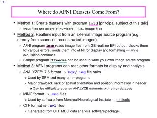
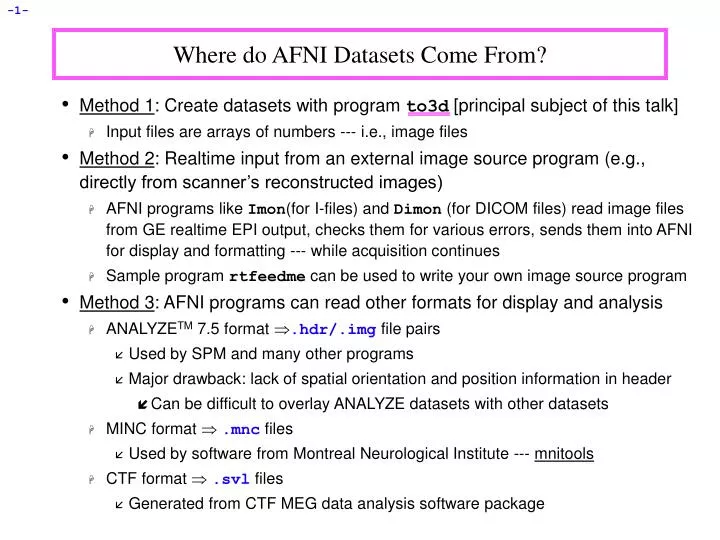
Where do AFNI Datasets Come From?. Method 1 : Create datasets with program to3d [principal subject of this talk] Input files are arrays of numbers --- i.e., image files Method 2 : Realtime input from an external image source program (e.g., directly from scanner’s reconstructed images)

E N D
Where do AFNI Datasets Come From? • Method 1: Create datasets with program to3d [principal subject of this talk] • Input files are arrays of numbers --- i.e., image files • Method 2: Realtime input from an external image source program (e.g., directly from scanner’s reconstructed images) • AFNI programs like Imon(for I-files) and Dimon (for DICOM files) read image files from GE realtime EPI output, checks them for various errors, sends them into AFNI for display and formatting --- while acquisition continues • Sample programrtfeedme can be used to write your own image source program • Method 3: AFNI programs can read other formats for display and analysis • ANALYZETM 7.5 format .hdr/.img file pairs • Used by SPM and many other programs • Major drawback: lack of spatial orientation and position information in header • Can be difficult to overlay ANALYZE datasets with other datasets • MINC format .mnc files • Used by software from Montreal Neurological Institute --- mnitools • CTF format .svl files • Generated from CTF MEG data analysis software package
Dataset stored as columns of ASCII-formatted numbers .1D and .3D files • Used to store datasets when knowing where the data points are in space isn’t important for the analysis • Example: node-wise analysis of group data on surfaces • Each column corresponds to one sub-brick • Each row corresponds to one voxel or node • .1D files: just columns of numbers • .3D files: contain an XML header with geometrical information • NIfTI-1 format .hdr/.img file pairs or .nii files • New format, modified from ANALYZE 7.5 compatible programs • Supposed to be mostly compatible with ANALYZE 7.5 compatible programs • Format finalized late 2003; will be supported by SPM, AFNI, FSL, Brain Voyager • Method 4: Output of most AFNI programs is AFNI-formatted datasets .HEAD/.BRIK file pairs • AFNI utility programs exist to re-write AFNI-formatted datasets into ANALYZE, MINC, and .3D formats • In the future, AFNI programs will be able to write out NIfTI-1 .nii formatted datasets directly
Creating AFNI Datasets with Program to3d • to3d reads image files -- each containing 1 or more 2D slices -- and assembles them into AFNI datasets • The collection of all the 2D slice data forms the .BRIK file • An AFNI dataset can contain a single slice • You must also provide to3d with some auxiliary data (for the .HEAD file): • Orientation of slices in space • Size of slices or of the voxels • Slice offset -- where is the dataset volume located in space? • For 3D+time datasets, you also need slice timing information • to3d ‘knows’ how to get some of this auxiliary information from image file headers for some image file formats: • ANALYZE 7.5 .hdr/.img pairs contain voxel size information • Siemens .ima Files contain voxel size and orientation information • GEI. Files contain voxel size and orientation information • DICOM Files contain lots of relevant information • But manufacturers’ variations on DICOM are frustrating
to3d runs in two modes: • Command line mode: you provide all auxiliary information on command line • Graphical interface (GUI) mode: you provide auxiliary information by filling out an on-screen form • Sample Study: data from NIH GE 3Tesla Scanner • Files stored in directory AFNI_data1/ • Anatomical (SPGR) data 3D dataset (no time; 1 sub-brick) • 124 sagittal slices in subdirectory SPGR_anat/ • Functional (EPI) time series data 3D+time dataset (110 sub-bricks or time pts) • 2970 images (27 sagittal slices, 110 reps) in subdirectory EPI_run1/ • Visual motion task: Videos of moving humans and tools (Beauchamp et al, 2002): High Contrast Moving Grating Low Contrast Moving Grating Moving Human Moving Tool
NIMH-LBC--Methods FMRI ResearchRUN DATA Exp Code: DD Date/Time: March 20, 2000 9 am Investigator: Mike B. Scanner:3T Coil: Wong/MAI/ GE ANAT Scan1: Type: SPGR /FSE/MPIR TE(ms): TR(ms):Flip: FOV(mm): 240 Matrix: 256x256 #slices: 124 Plane: Ax/Cor/ Sag Thickness(mm): 1.2 First: 70.0 L Last: 77.6 R EPI Scan: GE-EPI /SE-EPI/ GE RT EPI TE(ms):____ TR(ms): 2.5 sec Flip:___ Plane: Ax/ Cor/ Sag FOV(mm): 240 Matrix:64 Thickness(mm): 5.0 #slices: 27 (110 reps each) First: 69.0 R Last: 61.0 L • Experiment log, taken at scanner:
Using to3d to assemble the SPGR dataset: • cd AFNI_data1/SPGR_anat change directory, to get at images • ls to see what files are there (should see I.001 . . . I.124) • to3d I.* run to3d, reading in all the images files --- GUI pops us: • to3d understands GE I.* files, and so has filled in some of the GUI • Note: z-origin field 70.0 L corresponds to experiment log
To check images that were just input, click the[View Images] button in the to3d GUI • Window is the same as the AFNI image viewer • Slider below image lets you move between slices • In this example, to3d has all the information needed from the I.* headers • All you need to do is supply the data Prefix , then press [Save Dataset] • Look at the bottom right of the to3d GUI for these controls • I suggest the prefix anat • Dataset files anat+orig.HEAD and anat+orig.BRIK will be created • Then press [quit] button twice to exit to3d GUI • Script version (no GUI): to3d -prefix anat I.* would create a dataset with no user intervention • Later: will give a more complicated example of assembling data from ‘naked’ image files, where no header information is available
Using to3d to assemble the EPI 3D+time dataset: • cd ../EPI_run1 ---> change directory to get at images • ls ---> to see what files are there (should see files I.0001 . . . I.2970) • We do not just do to3d I.* to create a 3D+time dataset • For historical reasons, the time-axis information must be given on the to3d command line. • Cannot be modified from the GUI • Command line: to3d -time:zt 27 110 0 alt+z I.* • -time:zt slices usually presented in order of space (z), then time (t) • -time:tz is needed at some sites • If in doubt, do to3d I.* or aiv I.*, use viewer to look at slices and see their order [aiv = AFNI Image Viewer program] • 27 110 there are 27 slices in z and 110 in t (2970 total) • 0 the TR for volume acquisition will be read from the image headers • If not available, could put 2.5s or 2500 instead of this 0 • alt+z slices are gathered in alternating order in the +z direction • Most EPI acquisitions are really 2D multislice, spread out through time • AFNI header can contain information about slice timing offsets • Other possible modes: zero (for 3D), @filename (to specify each slice)
Outliers are data values that are very different from other values in the same time series • to3d reports sub-bricks (time points) that have a lot of outliers • You should use AFNI to look at these time points to see if there are major problems (e.g., head motion, scanner artifacts) • to3d -skip_outliers option lets you skip the outlier detection step • Utility program 3dToutcount can also report outliers and can even make a dataset with the ‘outlier-ness’ of each voxel value Sample data time series with potential outlier
The outlier becomes much more obvious when the first three time points of the time series (which show possible scanner artifacts) are removed:
In this example, the EPI and SPGR datasets are both sagittal slices. However, AFNI can work with SPGR/EPI datasets that have different planes (e.g., if SPGR is coronal and EPI is axial) • Programs 3dresample and 3daxialize can rewrite datasets in new orientations • Note slice thickness and slice offset (“z origin”) • Values match experiment log (that’s good) • Time information is displayed in GUI, but not editable • Have set “Type of Anatomy” to “Echo Planar” • Just acts as a reminder to user • Again, fields in the GUI were filled from the I.* headers • Script version: to3d -time:zt 27 110 0 alt+z -prefix epi_r1 I.* • Program 3drefit can be used to change some header items in an AFNI dataset after it is created • Example: 3drefit -TR 1s epi_r1+orig will change the TR of the dataset to 1 second
Creating New AFNI 3D+time Datasets with Program Imon • Imon can be run during a scanning session on a GE scanner, to monitor the collection of time series I.* files. The user is notified of any missing or out-of-sequence slices • Imon can also be run separate from scanning, either to verify the integrity of I.* files, or to create AFNI 3D+time datasets by using the -GERT_Reco2 option • Imon is run in command line mode • The -GERT_Reco2 option is added to the command line so that I.* files examined by Imon can then be assembled into an AFNI 3D+time dataset • When not being used in real-time mode, the -quit option is added so that Imon will terminate after processing all of the I.* files
Why not use to3d directly to create AFNI datasets? • EPI images collected using GE’s real time EPI sequence are saved in a peculiar fashion • Only 999 image files can be stored in a single directory • If a run consists of 110 volumes of 27 slices each, we have 2970 image files • With a limit of 999 I.* files per directory, a run made up of 2970 images would have to be saved in 3 separate directories (numbered001/, 021/, and041/): • E.g., 001/I.028…I.999 + 021/I.001…I.999 + 041/I.001…I.999 = 2970 I.* files total • The second run would be stored in directories 061/I.001101/I.973, the third run in 101/I.974161/I.946, and the nightmare continues… • This setup already makes it difficult to delineate between runs. Now image what happens if the scanner hiccups, if you stop a scan in the middle and start a new one, or start collecting scans with a different number of slices! • Imon attempts to identify complete scans from the images in those directories. It also monitors missing or out-of-order images, and generates the commands necessary to turn them into AFNI bricks using the script GERT_Reco2
Using Imon to assemble the EPI 3D+time datasets • cd ../EPI_manyruns change directory to get at GE subdirectories containing images • ls to view the GE subdirectories containing 4 runs worth of I.* files • Directories are numbered in multiples of 20 (default naming system used by the GE scanner): 001/ 021/ 041/ 061/. . . 201/ 221/ • Command line: Imon -start_dir 001 -GERT_Reco2 -quit • -start_dir specifies the starting directory where Imon will begin monitoring the images. In this example, our start directory is 001/ • -GERT_Reco2 will create a script called ‘GERT_Reco2’, similar to the one that program Ifile creates (for more info on Ifile, type Ifile -help). • The GERT_Reco2 script may be run to create the AFNI datasets corresponding to the I.* files • -quit will terminate Imon, after all image files have been examined, • If -quit is not used, the program will forever wait for more images, until <ctrl-c> is used to terminate the program • For a full list of Imon options, type Imon -help
Output from Imon command: • Imon will search for missing or out-of-order images. • Any errors will be noted on the screen • The starting point for each run is reported at the end of Imon’s examination run# 1: volumes 110, first file = 001/I.028run# 2: volumes 110, first file = 061/I.001run# 3: volumes 110, first file = 101/I.973run# 4: volumes 110, first file = 161/I.946
ls EPI_manyruns to view the newly created GERT_Reco2 script • This script contains the commands that will automatically create bricks from the complete scans and store them in a newly created subdirectory called afni/ • To run the script, type ./GERT_Reco2 • cd afni to get at datasets • ls to view the AFNI 3D+time datasets: Outbrick_r1+orig.HEAD Outbrick_r1+orig.BRIK Outbrick_r2+orig.HEAD Outbrick_r2+orig.BRIK Outbrick_r3+orig.HEAD Outbrick_r3+orig.BRIK Outbrick_r4+orig.HEAD Outbrick_r4+orig.BRIK
Processing DICOM Image Files with Dimon • NIH - new file format (2005): • Recently, the file format for images coming out of the GE scanners at the NIH have changed from I-files to DICOM. • Hence, the images are no longer saved as I.0001, I.0002,…etc. Instead, they appear with a .dcm suffix. For example: Anatomical Data: Time Series (EPI) Data: 3DMPRAGE-00001.dcm HeadAx2DGRE-00001.dcm 3DMPRAGE-00002.dcm HeadAx2DGRE-00002.dcm 3DMPRAGE-00003.dcm HeadAx2DGRE-00003.dcm . . . . . . 3DMPRAGE-00124.dcm HeadAx2DGRE-02280.dcm • The .dcm suffix appears for both anatomical and time series data. • Irrespective of whether you’re dealing with I.* files or *.dcm files, programs like to3d still work in the same way:to3d -prefix fred_anat I.* to3d -prefix fred_anat *.dcm
Processing DICOM Image Files with Dimon • What is Dimon? • Dimon is an AFNI program (by Rick Reynolds) intended to be run in real time (i.e., during a scanning run), to monitor the collection of DICOM image files. The user will be notified of any missing slices or any slices that are acquired out of order. • Dimon also communicates with the realtimeplugin in afni, allowing users to: • monitor subject head motion • create AFNI datasets. • Dimon can also be used offline (i.e., away from the scanner), either to verify the integrity of DICOM files, or to create AFNI 3D and 3D+time datasets by using the -GERT_Reco option (or you can use to3d). • Type Dimon -help for more information
Using Dimon in Real Time • During a scanning session, Dimon looks for potential problems with the output image files. Optionally, Dimon can be used to send the images (collected into volumes) to afni’s realtime plugin. • At the NIH, Dimon is invoked for both of these purposes automatically. • If Dimon has established a TCP connection with the real-time plugin to afni, then it will send each volume to the plugin, and will notify afni when a single run has ended. Note that afni will generally be running on a separate computer, not the scanning console where Dimon runs. • The realtime plugin will show the volumes in afni as they arrive, along with a 3-D registration graph, allowing users to monitor subject motion. • Each EPI run (or anatomical scan) will be stored as a separate AFNI dataset, created by the realtime plugin. • In this class example, these datasets are stored in the directory realtime.afni/
Overview of Real Time Processing at the NIH • Dimon and afni are invoked automatically (via scripts written by Jerzy Borduka). No user intervention is required. • The AFNI datasets created by afni’s real-time plugin are available for the users to download. • Separately, all DICOM files are passed to the DICOM catcher (part of the packrat utilities, organized by John Ostuni). The catcher organizes the files into a directory tree, with useful filenames, and then creates a .tgz package of it. • In this class example, the .tgz file called phantom_2005.08.02-14348.tgz was extracted: cd dicom/dicom.catcher/ cd phantom_2005.08.02-14348/2005_08_02-14348 ls 001/ 002/ 003/ ls 001/ls 002/ ls 003/ 3PLANELOC-00001.dcmHeadAx2DGRE-00001.dcm T2AxialACPC-00001.dcm 3PLANELOC-00002.dcm HeadAx2DGRE-00002.dcm T2AxialACPC-00002.dcm 3PLANELOC-00003.dcm HeadAx2DGRE-00003.dcm T2AxialACPC-00003.dcm . . . . . . . . . 3PLANELOC-00009.dcm HeadAx2DGRE-02280.dcm T2AxialACPC-00025.dcm
Using Dimon in Real Time(continued) • Once the DICOM files have been sorted and stored in the proper sub-directories, the images are copied over to AFNI (via network connection), where the AFNI RealTime Plugin assembles the images into 3D or 3D+time datasets (.HEAD/.BRIK files). • These datasets are saved in a directory called realtime.afni/ • Class Example: cd AFNI_data1/dicom/realtime.afni/ cd E14348 ls epiRT_scan_2#001+orig.HEAD epiRT_scan_2#001+orig.BRIK fse-xl_scan_3#001+orig.HEAD fse-xl_scan_3#001+orig.BRIK scan1 scan2 scan3 3D+time dataset,derived from images in sub-directory dicom.catcher/…/002/ 3D dataset, derived from images in sub-directory dicom.catcher/…/003/ Text files containing header information about the 3-plane localizer (scan1), the epi run (scan2) and the anat (scan3)
Using Dimon Off-Line • Sometimes, it may be necessary to run Dimon manually from the command line. • Suppose you receive some DICOM files that are obviously not sorted in the proper sequential order. For example: ls JOE_SCHMO/002 T2Axial-1.dcm T2Axial-10.dcm T2Axial-100.dcm T2Axial-2.dcm T2Axial-20.dcm T2Axial-200.dcm T2Axial-3.dcm T2Axial-30.dcm T2Axial-300.dcm T2Axial-4.dcm . . . • The problem here is that the image number for each slice is not “zero-padded” (e.g., T2Axial-1.dcm instead of T2Axial-00001.dcm). • When non-zero-padded files are alphabetically sorted, you get this result. • Use the -dicom_org option in Dimon to re-sort them by the sequential slice and time order. • To then assemble the images into an AFNI dataset, include the -GERT_Reco option on the Dimon command line.
Example of Dimon : Dimon -infile_pattern ‘002/T2Axial*.dcm’ \ -dicom_org -GERT_Reco -quit • Output from Dimon command: • DICOM files are sorted (non-DICOM files are ignored). • Dimon looks for missing or out-of-sequence DICOM files. • Volume information is presented when Dimon terminates (-quit or ctrl-c).
Explanation of Dimon arguments and options : Dimon -infile_pattern ‘002/T2Axial*.dcm’ \ -dicom_org -GERT_Reco -quit • -infile_pattern: This argument tells Dimon where the DICOM files of interest are located, and how they are labeled. In this case, the DICOM files are found in directory 002/ and they all begin with the name “T2Axial” and end with the “.dcm’ suffix. • -dicom_org: This option tells Dimon to read the files specified by the -infile_pattern argument, and to determine if they are indeed DICOM files, and if so, to organize them in an ordered list of files per run. • -quit: will terminate Dimon, after all image files have been examined, • If -quit is not used, the program will forever wait for more images, until <ctrl-c> is used to terminate the program • -GERT_Reco: This option creates the GERT_Reco_dicom script in the same directory that Dimon was run. To create AFNI datasets, just execute this script: • ./GERT_Reco_dicom or tcsh GERT_Reco_dicom • The result is an AFNI dataset created from the images in 002/ • OutBrick_run_002+orig.HEAD • OutBrick_run_002+orig.BRIK
Assembling ‘Naked’ Images into AFNI Datasets • ‘Naked’ image image file without header data that AFNI understands • User must supply geometrical information to to3d • This is when the written experiment log is critical! • The SPGR_naked/ directory contains the same SPGR images as before, but stripped of all header information • Each file has 131072 bytes = 256 x 256 16-bit integers (‘shorts’) • cd ../../SPGR_naked (to get at images N.001...N.110), then to3d N.* to3d WARNING: 389958 negative voxels (4.79862%) were read in images of shorts. It is possible the input images need byte-swapping ** I recommend that you View Images. **
On Linux/Intel computers: the peculiar appearance of images shows that something is wrong: • MR images from scanners that are stored as shorts: 2 bytes per number • Like a 2-digit decimal number: “93” means “9 x 10 + 3” • By universal custom, we write the “9” first • Could also write the same number as “39” (if we had a different custom) • Customs for computers are not so universal • Sun and SGI systems store 2 byte numbers in reverse order from Intel • Result is that numbers are mangled (and some show up as negative) • Solution: press to3d’s[Byte Swap[2]] button and images are fixed! Linux/Intel computers SGI/Sun/etc. computers
Same to3d control panel (without negative voxel warning): • Above the double line: must fill out 3 types of geometry information • Left column: orientation of the dataset axes • Middle column: size of the dataset images or voxels • Right column: offset of the first slice
Screen shot above shows correct orientation for this dataset • Use the image viewing window to judge how images are laid out • Click the arrows to scroll through the 6 possible options for each orientation to set correct values • “x orientation” of dataset is across the screen (Anterior to Posterior) • “y” orientation of dataset is down the screen (Superior to Inferior) • “z” orientation” of dataset is in increasing slice order (from Left to Right) • Must know subject’s right from left (from experiment log sheet or vitamin E tablet placed on one side of the head) • Determine this by using the slider at the bottom of image window
To set dataset geometrical size/location, experiment log sheet is essential • Screen shot above shows setting slice thickness to 1.2 mm • Default Field of view (FOV) of 240 mm is correct for these images • The default voxel geometry is “cubical”, which is incorrect for this example • Must set geometry to “square” (x size = y size, z size different) • Then set “z voxel size” to correct value (by typing in box) • Screen shot shows setting of first slice to 70.0 mm in Left (L) direction • Default is that slices are centered in the magnet • This default is usually not the case in the z direction • Click “z axis centered” off • Enter offset (here 70.0 mm) into the “z origin” box
Final required steps: • Enter prefix for new dataset into [Prefix] text box at lower right of to3d control window • Choosing a good prefix is important for keeping datasets organized • Press [Save Dataset] button • Press[quit] (twice) to exit to3d • The new dataset files should show up when you use command ls • For organizational purposes, you may want to move your datasets to some other directory
Geometry parent lets you copy the geometry data from a pre-existing dataset and apply it to the dataset now under construction • Enter name of pre-existing dataset into [Copy geometry of this dataset] field • If in another directory, you must include that in the filename • When you press ‘Enter’ or move the cursor from the text-entry field, to3d tries to read geometry parent dataset header • If geometry parent has same spatial dimensions as current dataset, all geometry fields will be filled out • Does not affect the time fields, which must still be set using -time:zt or -time:tz on the command line • Geometry parent very useful when constructing multiple EPI datasets from a single scanning session • Using to3d in command line mode • You can specify all needed inputs to to3d by using command line options • For a full list of options, type to3d -help • If enough information is present on command line to define a dataset, then the GUI will not be opened, and the dataset will be written to disk • If the command line is incomplete, then the GUI will be opened
For the SPGR dataset example (‘naked’ image files): to3d -xFOV 120A-P -yFOV 120S-I -zSLAB 70.0L-77.6R \ -prefix anatNaked -2swap -spgr N.* • -xFOV 120A-P says that the x axis of the images runs from 120 mm Anterior to 120 mm Posterior • -yFOV 120S-I says that the y axis of the images runs from 120 mm Superior to 120 mm Inferior • -zSLAB 70.0L-77.6R says that the z axis of the slices runs from 70 mm Left to 77.6 mm Right • FOV refers to the coordinates of the outer edge of the first voxel to the outer edge of the last voxel along the relevant axis (x and y, in most cases) • SLAB refers to coordinates of the center of the outermost voxels (z=slice direction, in most cases) • -prefix anatNaked gives the prefix for output dataset filenames (in this case, anatNaked+orig.HEAD and anatNaked+orig.BRIK) • -2swap means to byte-swap the images while reading them • -spgr means to label this data as being of SPGR (SPoiled GRass) type • N.* means to read the images from the files whose names start with string “N.” and end with anything (“*” is a wildcard)
For the EPI dataset example (if image files were ‘naked’): to3d -xFOV 120S-I -yFOV 120P-A -zSLAB 69.0R-61.0L -2swap \ -time:zt 27 110 2500 alt+z -prefix epiRun1 -epan I.* (this is all on one command line) • Options (with their arguments) can appear in any order • Input image filenames always appear last (i.e., I.* or *.dcm) • Conclusion • With practice, command line usage for to3d becomes more useful than the GUI • Usually need to create many datasets at once • Can put commands in a script file and execute them • Then edit the file to change a few things, and run it again • Just create the file with your favorite UNIX text editor (emacs, nedit, vi), typing each command on a separate line • Long commands can be split across multiple lines by ending all but the last line with the “\” character • There must not be a blank after the “\”!!! • You can execute a script file by typing a command like tcsh <filename>, which just means to read commands from “filename” • As time goes on, you build up a set of scripts that automate various tasks for you, and ensure you do things the same way each time