Download
1 / 9
90 likes | 482 Views
ES 202 Fluid and Thermal Systems Lecture 28: Drag Analysis on Flat Plates and Cross-Flow Cylinders (2/17/2003). Road Map of Lecture 28. Finish up drag analysis over a flat plate Visualization from MMFM

E N D
ES 202Fluid and Thermal SystemsLecture 28:Drag Analysis on Flat Plates and Cross-Flow Cylinders(2/17/2003)
Road Map of Lecture 28 • Finish up drag analysis over a flat plate • Visualization from MMFM • flow separation over a sphere at high Reynolds numbers (serves as motivation to drag analysis) • flow pattern over a cylinder from low to high Reynolds numbers • Drag analysis on a cross-flow cylinder in open air • Drag analysis on a cross-flow cylinder in a wind tunnel • emphasize the difference between the “open air” problem and the “wind tunnel” problem ES 202 Fluid & Thermal Systems
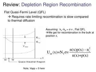
Drag Analysis over a Flat Plate • Consider a uniform flow over a flat plate and assume the velocity distribution within the boundary layer follows a 1/7-power law: Determine the total drag on a flat plate of length L and width w. U y d x L ES 202 Fluid & Thermal Systems
Main Points • Boundary layer slows down the flow next to the plate causing a mass and momentum deficit. • The mass deficit in the boundary layer causes mass to flow out of the top boundary, governed by mass conservation. • As the mass flows out of the top boundary, it takes streamwise momentum along with it. • In open air, the pressure is atmospheric on all control surfaces, leaving the drag force on the bottom surface the only force in the streamwise direction. • In the momentum balance equation, two integrations need to be performed to find out the mass and momentum outflow on the exit surface. The integration procedure is not necessary in a simplified one-dimensional analysis . ES 202 Fluid & Thermal Systems
Visual Learning • Motivational visualization: flow separation behind a tennis ball at high Reynolds numbers from MMFM • high-light the wake region • Can you use Bernoulli’s equation in the wake region? Why? • Flow pattern over a cross-flow cylinder at various Reynolds numbers from MMFM • at low Reynolds numbers, no separation behind the cylinder • at increasingly high Reynolds numbers, flow separation becomes more severe. • emphasize the Reynolds number dependency of the flow • reinforce the meaning and physical significance of Reynolds number ES 202 Fluid & Thermal Systems
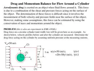
U U wake region 2d 2d U 2d d 2d U U Drag Analysis on a Cross-Flow Cylinder in Open Air • In an experiment to determine the drag on a cylinder due to a uniform cross-flow U, a circular cylinder of diameter d was immersed in a steady, two-dimensional incompressible flow in open air. Measurements of velocity and pressure were made at the boundaries of a fixed control volume shown below. The pressure was uniform over the entire control surface. The streamwise velocity component is indicated in the following figure. Based on the measured data, determine the drag coefficient on the cylinder (based on the projected frontal area.) ES 202 Fluid & Thermal Systems
Main Points (Similar to Flat Plate) • Similar to the boundary layer over a flat plate, the wake behind a cylinder causes a mass and momentum deficit. • The mass deficit in the boundary layer causes mass to flow out of the top and bottom boundaries, governed by mass conservation. • As the mass flows out of the top and bottom boundaries, it takes streamwise momentum along with it. • In open air, the pressure is atmospheric on all control surfaces leaving the drag force on the cylinder surface the only force in the streamwise direction. • In the momentum balance equation, two integrations need to be performed to find out the mass and momentum outflow on the exit surface. The assumed linear velocity profile is easier to be integrated, as compared with the 1/7-power law in a boundary layer. ES 202 Fluid & Thermal Systems
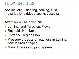
upper wall of wind tunnel wake region 2d 2d U 2d d 2d lower wall of wind tunnel Drag Analysis on a Cross-Flow Cylinder in a Wind Tunnel • In an experiment to determine the drag on a cylinder due to a uniform cross-flow U, a circular cylinder of diameter d was immersed in a steady, two-dimensional incompressible flow in a wind tunnel. Measurements of the velocity profile downstream of the cylinder were made as shown below. Assume the tunnel walls to be relatively frictionless, compared to the flow around the cylinder. Determine the drag coefficient on the cylinder (based on the projected frontal area.) ES 202 Fluid & Thermal Systems
Main Points • The major difference between the “open air” problem and the “wind tunnel” problem is due to the flow confinement effects from the top and bottom walls. • The cylinder blockage causes the outer inviscid flow to speed up. The exit flow speed in the inviscid region can be obtained by mass conservation. • The flow acceleration causes pressure to drop. The corresponding pressure drop can be obtained quantitatively by the Bernoulli’s equation. • In the wind tunnel problem, the drag force on the cylinder surface is no longer the only force in the streamwise direction. There is an additional force due to pressurevariation. • Again, two integrations need to be performed to find out the mass and momentum outflow on the exit surface. ES 202 Fluid & Thermal Systems