Download
1 / 20
200 likes | 219 Views
Digital Electronics Tutorial: Word Problems Solutions. Alarm Clock.

E N D
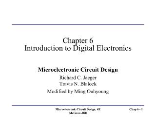
Digital ElectronicsTutorial: Word Problems Solutions ELEC1041 – Word Problems - 1
Alarm Clock • Consider the design of a simple digital alarm clock. The clock can display the current time in HH:MM notation along with a single LED that is illuminated when the time is PM (it is NOT lit up in the AM). There are several control inputs for setting the current time and the alarm time. The TIME SET HH button allows you to rapidly advance through the hours 1 through 12 AM and 1 through 12 PM. The time advances one hour for each time the button is pressed. The TIME SET MM button does the same thing for the minutes 00 through 59. In addition, the clock has a toggle input that indicates CLOCK in one position and ALARM in the other. This refers to which time is being set by the TIME SET buttons: either the current time (CLOCK) or the alarm time (ALARM). If the ALARM button is set, the clock displays the last set alarm time. Finally, there is another input controlled by a push button: ALARM ON when pushed in and ALARM OFF when popped out. Your job is define the state diagram for the clock controller. It should support normal clock display (when CLOCK is set), alarm display (when ALARM is set), set current time (CLOCK + TIME SET buttons), set alarm time (ALARM + TIME SET buttons), and of course, the alarm should sound when current time equals alarm time. (a)Identify your inputs, outputs, and name and describe your states. (b)Draw a symbolic state diagram for your design, labeling all state transitions. ELEC1041 – Word Problems - 2
DiplayMode DiplayMode Alarm Clock Solution (1/8) • In addition, the clock has a toggle input that indicates CLOCK in one position and ALARM in the other. This refers to which time is being set by the TIME SET buttons: either the current time (CLOCK) or the alarm time (ALARM). If the ALARM button is set, the clock displays the last set alarm time. Current Time: 10:23 PM Current Time Mode AM/PM Indicator. Light indicates PM Alarm Time: 06:30 AM Alarm Time Mode ELEC1041 – Word Problems - 3
Alarm Clock Solution (2/8) • The TIME SET HH button allows you to rapidly advance through the hours 1 through 12 AM and 1 through 12 PM. The time advances one hour for each time the button is pressed. SetTimeHH SetTimeHH SetTimeHH SetTimeHH ? SetTimeHH SetTimeHH Design Assumption ELEC1041 – Word Problems - 4
SetTimeMM Alarm Clock Solution (3/8) • The TIME SET MM button does the same thing for the minutes 00 through 59.. SetTimeMM SetTimeMM SetTimeMM SetTimeMM SetTimeMM ? Design Assumption ELEC1041 – Word Problems - 5
Alarm Clock Solution (4/8) • Finally, there is another input controlled by a push button: ALARM ON when pushed in and ALARM OFF when popped out. Assumption: When the alarm is NOT set, pressing the alarm set button turns ON the alarm (AlarmSet = 1). (1)When the alarm is set and sounds, pressing the alarm set button again turns off the alarm (AlarmSet = 0). Alarm Sounds = ELEC1041 – Word Problems - 6
Alarm Clock Solution (5/8) (a)Identify your inputs, outputs, and name and describe your states. Inputs: TimeSetHH 1 incrementing HH of clock or alarm by 1 TimeSetMM 1 incrementing MM of clock or alarm by 1 DisplayMode 0 Clock , 1 Alarm AlarmSet 1 alarm is set Outputs: HH++ HH is advanced by 1 MM++ MM is advanced by 1 Alarm sounds ELEC1041 – Word Problems - 7
Alarm Clock Solution (6/8) (b)Draw a symbolic state diagram for your design, labeling all state transitions. States: Clock normal clock display mode where HH and MM of current time can be adjusted. Alarm – alarm display where HH and MM can be set for alarming time. Alarm Sounding – Alarm sounds at this state ELEC1041 – Word Problems - 8
Alarm Clock Solution (7/8) (b)Draw a symbolic state diagram for your design, labeling all state transitions. TimeSetMM/MM++ TimeSetHH/HH++ TimeSetMM/MM++ TimeSetHH/HH++ DispalyMode=1 Clock Alarm DispalyMode=0 DispalyMode=0 & AlarmSet = 0 AlarmSet = 1 & HH:MM (clock) = HH:MM (alarm)/ Alarm sounds AlarmSet = 1 & HH:MM (clock) = HH:MM (alarm)/ Alarm sounds DispalyMode=1 & AlarmSet = 0 Alarm Sounding [Alarm sounds] ELEC1041 – Word Problems - 9
Alarm Clock Solution (8/8) (b)Draw a symbolic state diagram for your design, labeling all state transitions. TimeSetMM/MM++ TimeSetHH/HH++ TimeSetMM/MM++ TimeSetHH/HH++ DispalyMode=1 Clock Alarm DispalyMode=0 DispalyMode=0 & AlarmSet = 0 DispalyMode=1 & AlarmSet = 1 & HH:MM (clock) = HH:MM (alarm)/ Alarm sounds DispalyMode=0 & AlarmSet = 1 & HH:MM (clock) = HH:MM (alarm)/ Alarm sounds DispalyMode=1 & AlarmSet = 0 Alarm Sounding [Alarm sounds] ELEC1041 – Word Problems - 10
Cloth Dryer • Captain of the Enterprise has one of those incredibly complicated European Miele clothes dryers. The machine has dryer settings for three mutually exclusive option settings, one of which MUST be selected: Cotton fabrics (Extra Dry, Normal+, Normal, Hand Iron, Hand Iron Damp, Machine Iron Wet), Permanent Press fabrics (Normal+, Normal, Hand Iron), or Timed Drying (15 minutes, 20 minutes, 30 minutes). Presumably the dryer has some kind of embedded humidity sensor that can determine just how wet the wash is, and when this sensor value is reached, the dryer can advance to the next phase. This is Cool Down, which turns off the drying action until the clothes reach a predetermined “cool” temperature. The final stage is Anticrease, which intermixes a tumbling action with periods for which nothing happens (e.g., 10 second spin followed by 30 seconds of nothing). This goes on for five minutes. The machine then advances to Stop, and is ready for the next load. (a)Identify your inputs, outputs, and name and describe your states. (b)Draw a symbolic state diagram for your design, labeling all state transitions. Write down any additional assumptions you are making. ELEC1041 – Word Problems - 11
Cloth Dryer Solution (1/2) (a)Identify your inputs, outputs, and name and describe your states. Inputs: Externally: any of the drying options, such as: cotton fabrics, permanent press fabrics, timed drying and their settings such as: Extra Dry, Normal+, Normal, Hand Iron, Hand Iron Damp, Machine Iron Wet Internally: information from temperature and humidity sensors, timer. Output: Lights indicating which stage it is in, i.e. drying, cool down, stop States: Different drying options, cool down and stop states. ELEC1041 – Word Problems - 12
Cloth Dryer Solution (2/2) (b)Draw a symbolic state diagram for your design, labeling all state transitions. Write down any additional assumptions you are making. cotton Timed drying Idle … Extra N+ N Hand I H I Damp Machine I W WET WET WET WET WET WET Permanent press NOT WET Timer expired Cool Down … cool Not cool Anti Crease Timer not expired ELEC1041 – Word Problems - 13
Traffic Light Controller (1/3) • Consider the following variation on the classical traffic light controller. The intersection in question is shown in Figure below. • A Street runs north-south, B Street runs east-west, and C Street enters the intersection from the southeast. • A Street is quite busy, • It is frequently difficult for cars heading south on A to make the right turn onto either B or CStreets. • In addition, cars rarely enter the intersection from C Street. A Right turn path B C ELEC1041 – Word Problems - 14
Lights as seen in other directions Lights as seen in from A North heading South Traffic Light Controller (2/3) • Design a traffic light state diagram for this three way intersection to the following specifications: • There are 5 sets of traffic lights facing cars coming FROM A North, A South, B East, B West, and C Southeast respectively. • The red, yellow, and green lights facing cars FROM A North, are augmented with a RIGHT TURN ARROW, which can be lit up as either green or not lit up at all. • The normal sequencing of light facing the cars coming from A North is: Arrow Green, Arrow Yellow, Traffic Light Green, Traffic Light Yellow, Traffic Light Red, and repeat. In other words, the Right Turn Arrow light is illuminated in every complete cycle of lights. ELEC1041 – Word Problems - 15
Traffic Light Controller (2/3) • However, it should be possible for the traffic going from north to south on A Street to cross the intersection even when the RIGHT TURN ARROW illuminated. Therefore, the Traffic Light Green should also be illuminated while the RIGHT TURN ARROW is lit up. • Cars travelling from the south to north on A Street (and all directions on B and C Streets) must see a red light while the RIGHT TURN ARROW is illuminated for the traffic heading south. • A car sensor C is embedded in C Street to detect whether a car is waiting to enter the intersection from the southeast. • A timer generates a long interval signal TL and s short interval signal TS when set by an ST signal. • Red and green lights are lit up for at least a TL unit of time. Yellow lights, the green arrow, and the yellow arrow are lit up for exactly a TS unit of time • The C Street lights cycle from red to green only if the embedded car sensor indicates that a car is waiting. The lights cycle to yellow then red as soon as there are no cars waiting. Under no circumstances is the C Street green light to be lit for longer than TL unit of time. ELEC1041 – Word Problems - 16
North facing C 5 3 South facing 3 3 East facing West facing Traffic Light Controller Solution (1/4) ELEC1041 – Word Problems - 17
Traffic Light Controller Solution (2/4) Reset/ST S0 G A TS/ST TS/ST TS’ S7 SE Y S1 Y A TS’ TS’ TL + C’/ST TS/ST TL’ . C S6 SE G TS . C’ S2 N-S G TL’ TS . C/ST TL/ST TL’ TS’ S5 E-W Y S3 N-S Y TS’ S4 E-W G Recall: NOT A = A = A’ = /A =\A TS/ST TL/ST ELEC1041 – Word Problems - 18
4 5 6 7 0 1 2 3 Y R R R R Y R R R R R G Y R R R R R G Y G,GA G,YA G R R G R R R R R R Traffic Light Controller Solution (3/4) State Numbers A Street North Facing Lights A Street South Facing Lights B Street East & West Facing Lights C Street South-east Facing Lights ELEC1041 – Word Problems - 19
+ Traffic Light Controller Solution (4/4) Jump Counters • Controller Implementation CLR, CNT, LD implemented via Mux Logic CNT CLR = CLRm + Reset CLR = /CLRm + /Reset 138 P 163 7 /S7 G2 T /S6 6 RCO G1 /S5 CLK 5 /S4 D 4 QD D /S3 3 C QC C OUTPUTS /S2 2 B QB B /CLRm /S1 1 /CLR A A QA /Reset /S0 0 /GA = /s0 /N-SG = /s0. /s1. /s2 /N-SY = /S3 /N-SR =/S4./S5./S6./S7 /S-NG = /S2 /S-NY = /S3 /S-NR = /S0./S1./S4./S5./S6./S7 /W-EG = /E-WG = /S4 /W-EY = /E-WY = /S5 /W-ER = /E-WG = /S0./S1./S2./S3./S6./S7 /CG =/S6 /CY = /S7 /CR = /S0./S1./S2./S3./S4./S5 LOAD /Reset Reset /CLR CLR Active Lo outputs: hi input inverted at the output Note that CNT is active hi on counter so invert MUX inputs! S0 S1 S2 S0 S1 S2 G G 151 151 /TS 0 E7 E7 /(TL + /C) 0 E6 E6 /CLRm /(TS.C) TS.C E5 E5 EOUT EOUT /TL 0 E4 E4 CNT /TS 0 E3 E3 /TL 0 E2 E2 /TS 0 E1 E1 /TS 0 E0 E0 ELEC1041 – Word Problems - 20