Download
1 / 18
200 likes | 377 Views
Alaska Space Grant Program. Alaska Research Cubesat Operating System. Gregg Christopher MSCS Graduate Project Presentation 3 11/22/2011. Introduction:. Alaska Research Cubesat (ARC) Started in Fall 2009 with a Space Systems Engineering course. Currently in Development; expect

E N D
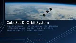
Alaska Space Grant Program Alaska Research Cubesat Operating System Gregg Christopher MSCS Graduate Project Presentation 3 11/22/2011
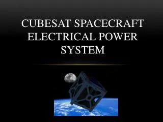
Introduction: • Alaska Research Cubesat (ARC) • Started in Fall 2009 with a Space Systems Engineering course. • Currently in Development; expect to fly in 2013. • First student-built spacecraft for UAF. • MS CS Project • Driven by ARC requirements. • A subset of full Command and Data Handling (CDH) functionality. • Collaborative project between CS/SWE and Engineering departments. *(Image Source: ARC1 CDR Presentation, 08/29/2011)
CubeSat in a Nutshell • Some Challenges: • Mechanical Design • Thermal Modeling • Power Budget • Attitude Determination and Control • Ground Communication • Computer Architecture • Error Handling *(Image Source: ARC1 CDR Presentation, 08/29/2011)
CDH System Overview ARCBus Devices Included in CDH Specification Electrical Power Subsystem (EPS) Supervisor/ Reset Circuit Dev/Debug Harness Power only I2C Command Bus SPI Data Bus Interrupt Lines Supervisor Inspection / Reset Bus Power Distribution Bus I2C, Power SPI, Power COMM Subsystem Master Controller Compatible I2C Device Compatible SPI Device Debug Port Command Uplink / Data Downlink Other Subsystems All subsystems share a set of electrical and software specifications. One subsystem is designated as Master Controller. All subsystems are connected to a Supervisor circuit responsible for reset-based fault recovery. Command and Data are transmitted over a shared dedicated bus. Subsystems may be tested independently according to system specification. 4
Imagine Failure • Expected Failure Modes are Single Event Upset (SEU) bit flips, and Latchup Events. • Within the failure mode model, assume errors are chosen adversarially to induce the worst-case scenario. • Use this mindset to steer toward simpler choices. (Source: http://nasawatch.com)
Major Areas of This Project • System and Software Engineering • Architecture Requirements • Design Review Process • Physical Assembly • More Design Review Process • Re-Scoping for MS Project • Project Hardware Creation • Finally, Programming!
+ Multi-master I2C exchange + Representative Commands - Needs robustness - Needs “real” command structure + Works, Repeatable, Simple - Accurate space environment? + Automated Test Harness + PC-Controlled Failure and Recovery! Failure: I still had to make new circuits and other hardware workarounds Revisiting the Scope Guidance from Advisor: • Demonstrate: • Command exchange • Error simulation • Testing Capability • Defer: • Complete command table. • Complicated command interactions. • Other features essential for cubesat, but not for minimally functional CDH concept. • Anything requiring more hardware development.
Implementation Progress • Functional in most areas. • Many areas not yet complaint with CDR. • Following Strategy From Talk 2: • Basic unified firmware. • Tools for automation. • Representative command set • Test case generation.
Test Harness Archictecture PC Software Interactive Toolset Automated Test Rig Optional Integration Manual or Scripted Command Exchange Test Scenario Generator Dev Board Emulator Class Standalone Controller FT245 Library Serial Library Test Hardware Reset Control Comm Interface Subsystem Peripheral Subsystem Peripheral Dev Board Dev Board Dev Board ARC Bus Switched Power Supply
Test Command Table: • Set LED Pattern • Report LED Pattern • Remote Set LED Pattern (Across Boards) • Set Work Area Buffer Segment • Read Work Area Buffer Segment • Perform Calculation on Buffer • Send Buffer Segment to Other Board • Flip Bits (Intentionally corrupt memory)
Test Sequence Generation: • Commands are generally paired with verification commands. • Random or pre-programmed sequences of operations. • Vary the selection, speed and distribution of operations per test requirements. • Induce Simulated Single Upset Events. • Automatically Reset on Error and Repeat. Test Harness Interface (dev boards unplugged)
Error Simulation: • Simulated Single Event Upset (SSEU) • Flip bits in addressable memory. • Register corruption will be harder. • Non-addressable volatile memory? • Error simulation does not replace other testing and review.
Error Mode Categorization: • Recoverable Error: Any change to memory that can be reverted to a previously known known state. (Currently only redundant memory.) • Immediate Action: correct and continue • Roughly 1-2% of SSEU result in this condition. (Trivial and uninteresting result.) • Non-Recoverable Error
Error Mode Categorization: • Non-Recoverable Error: Everything else that happens. • Recover via reset. • Currently very high. • High rate means that what I’m probably detecting are weaknesses in the firmware. • This shouldn’t be surprising! (First large project on platform) • Probably the lack of error detection/recovery in I2C Multi-Master implementation • Might also be bad interrupt programming. • Still a valuable result! These are errors that didn’t occur during manual, interactive testing.
Project Status Summary: • Developed: • Hardware and firmware that implement rudimentary CDH functionality. • PC software for automated and interactive testing. • Toolchain development to reduce the barrier to entry. • Drop-in testing environment for dev boards. • Tested: • Runs of firmware with sample command set for preliminary testing results.
Next Steps (This Project) • Deliver draft • Eliminate sources of systematic error • Improve error simulation • Characterize Space Environment • Validate with radiation-induced SEU and latchup events.
Next Steps (Cubesat) • Immediate need for CDH code for other system development. • An outcome of this MS Project is: I’ve done a lot of things wrong; help the group avoid these. • Robust μC firmware is exceedingly difficult. • Bring Supervisor Circuit in line with CDR Design • Establish Test Harness in the Lab
Thanks for Attending! Gregg Christopher: • gchristopher@gmail.com