Download
1 / 19
190 likes | 340 Views
Mechanical design, analysis and integration of pre-alignment systems for CLIC. M.Anastasopoulos / BE-ABP-SU. Contents. I. Introduction II. Mechanical Design - Typical workflow III. Completed and running projects IV. Future tasks. I . Introduction. 200 m. CLIC Pre-alignment

E N D
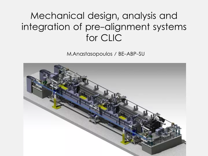
Mechanical design, analysis and integration of pre-alignment systems for CLIC M.Anastasopoulos / BE-ABP-SU
Contents I. Introduction II. Mechanical Design - Typical workflow III. Completed and running projects IV. Future tasks
I. Introduction 200 m • CLIC Pre-alignment • Components should be pre-aligned within a few microns over 200m • Overlapping stretched wires will provide a stable and determined alignment reference • cWPS sensors will perform measurements with respect to these wires • Actuators will re-adjust the components to their theoretical positions • Challenges in the Test-Modules • for the mechanical engineer • Simultaneous existence of various systems: vacuum, RF, stabilization, pre-alignment • Limited space for installation • Access and maintenance issues • Proper collaboration between systems designed by different people The metrological reference network of overlapping wires
II. Mechanical Design - Typical workflow Concept Integration 3D design Re-design Fabrication Installation Previously used system that needs to be modified
III. Completed and running projects • Support extemities of WPS and HLS sensors for CLIC Test-Module 3D design of proposed solution Simulation under working load for design optimization
Design, analysis & integration of additional components Deformation under working load (static) Stretching devices - fixed end Stretching devices - weight end Basic supporting system Optical WPS with fixation cWPS sensor with fixation Servo Inclinometer with fixation
Fabrication drawings and installation plans Top plate fabrication drawing Stretching devices assembly plan Complete system assembly plan Supporting block installation plan
Final solution for installation of WPS sensors, inclinometers, wire stretching devices
Support extremities integrated • at Test-Module level • Various modifications made to the initial design • Additional systems are foreseen to be installed in the future (HLS)
Adaptation of HydrostaticLeveling System (HLS) and water network for CLIC Test-Module HLS schematic Typical HLS Pot and a previous installation • Used to determine height differences • Based on communicating vessels principle • Air linkage between the stations for achieving the same pressure
HLS Pot assembly PS4 Valve Support assembly plan HLS Network installation plan
HLS network integrated • at Test-Module level • Fabrication of real components is in progress
Integration of NIKHEF RasChain system • Alternative alignment solution • Based on optical WPS sensors (laser) • Needs thermal insulation NIKHEF optical alignment system (current design under modifications) Integration of current version of the system (Laser sensors & thermal insulation)
Integration of an alignment system in a 5 DoFMockup • Will provide an evaluation platform for a 5 DoF system, based on cam movers A compact solution was adopted for sensor plates and stretching devices Actual installation at 927-TAP
Metrological Reference Network (MRN) Interconnecting bench Metrological Reference Network 200 m Overlapping stretched wire Interconnecting metrological plate • Currently proposed solution / still under evaluation • Limited space (~ 50 cm. width allowance inbetween the module’s girders) • Access for sensors and stretching devices maintenance • Minimum deformation of supporting plate