Download
1 / 25
250 likes | 656 Views

E N D
1. Good morning, my name is Elisabet Cap�n and I am here in representation of a group of my laboratory who has been working on the simulation of an IGCC (integrated gasification combined cycle) power plant. Concretely, the name of the presentation is �Integrated Environment for detailed modelling and evaluation of gasification processes for energy production� and it is in the frame of an European project called AGAPUTE (focused on advanced gas purification technologies for co-gasification targeted to clean power).Good morning, my name is Elisabet Cap�n and I am here in representation of a group of my laboratory who has been working on the simulation of an IGCC (integrated gasification combined cycle) power plant. Concretely, the name of the presentation is �Integrated Environment for detailed modelling and evaluation of gasification processes for energy production� and it is in the frame of an European project called AGAPUTE (focused on advanced gas purification technologies for co-gasification targeted to clean power).
2. 2 Once seen why IGCC power plants are interesting to study in the current time, we will be focused in the objectives, tools and layout of this project. Once seen why IGCC power plants are interesting to study in the current time, we will be focused in the objectives, tools and layout of this project.
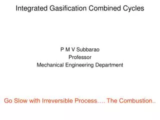
3. 3 An IGCC power plant, as we know, is a plant which includes gasification and a combined cycle to produce heat and power. The combination of these two known techniques has important advantages: Gasification contributes with feedstock and product flexibility. In the side of types of feedstocks, coal can be combined with biomass or wastes (it is concretely on this point where this work is focused), and as products, hydrogen or carbon monoxide can be enhanced, by modifying temperature and pressure conditions.
The use of the combined cycle implies a higher efficiency than in conventional thermal power plants (around 40-50%). A higher efficiency implies a less feedstock consumption (less cost), less emissions per unit of energy. It is a technology profitable in a lot of different technologique scenarios (easy of integration...).
Once seen why IGCC power plants are interesting to study in the current time, we will be focused in the objectives, tools and layout of this project. An IGCC power plant, as we know, is a plant which includes gasification and a combined cycle to produce heat and power. The combination of these two known techniques has important advantages: Gasification contributes with feedstock and product flexibility. In the side of types of feedstocks, coal can be combined with biomass or wastes (it is concretely on this point where this work is focused), and as products, hydrogen or carbon monoxide can be enhanced, by modifying temperature and pressure conditions.
The use of the combined cycle implies a higher efficiency than in conventional thermal power plants (around 40-50%). A higher efficiency implies a less feedstock consumption (less cost), less emissions per unit of energy. It is a technology profitable in a lot of different technologique scenarios (easy of integration...).
Once seen why IGCC power plants are interesting to study in the current time, we will be focused in the objectives, tools and layout of this project.
4. 4 (Leer exactamente lo que pone en la transparencia). Se puede decir que el tercer cuadro de los objetivos �is the final purpose of this work�. En el primer cuadro de objetivos comentar que �it implies a correct integration of individual units models, including pre-processing, gasification, purification processes and power generation�.
PRENFLO (redirected from Pressurized Entrained Flow (Process))
(Leer exactamente lo que pone en la transparencia). Se puede decir que el tercer cuadro de los objetivos �is the final purpose of this work�. En el primer cuadro de objetivos comentar que �it implies a correct integration of individual units models, including pre-processing, gasification, purification processes and power generation�.
PRENFLO (redirected from Pressurized Entrained Flow (Process))
5. 5 In the first one, they are represented the HP and IP steam circuits: water is heated by two sources: the cooling of the exhaust clean gas from the Brayton cycle and the refrigeration of the syngas from the gasifier.
In the second one: the LP steam circuit has only one heating source: the exhaust clean gas from the GT (gas turbine).
In the first one, they are represented the HP and IP steam circuits: water is heated by two sources: the cooling of the exhaust clean gas from the Brayton cycle and the refrigeration of the syngas from the gasifier.
In the second one: the LP steam circuit has only one heating source: the exhaust clean gas from the GT (gas turbine).
6. 6 The hypothesis considered in this project, can be divided into two groups, according to if they have been used to adapt the real conditions to the simulation environment (�modelling� assumptions) or if, in the other hand, they are assumptions adopted in the software.
Leer los puntos. En el primero, ELCOGAS is a real plant situated in Puertollano, near Madrid, in Spain. En el tercero, temperature and pressure conditions of the gasifier, se puede decir que es T around 1600� C, and P around 25 bar. The hypothesis considered in this project, can be divided into two groups, according to if they have been used to adapt the real conditions to the simulation environment (�modelling� assumptions) or if, in the other hand, they are assumptions adopted in the software.
Leer los puntos. En el primero, ELCOGAS is a real plant situated in Puertollano, near Madrid, in Spain. En el tercero, temperature and pressure conditions of the gasifier, se puede decir que es T around 1600� C, and P around 25 bar.
7. 7 En el primer punto, as they are defined as hypo-components, they are characterised by means of their composition ? ultimate analysis (% in weight basis of carbon, hydrogen, oxygen, nitrogen, sulphur, chlorine, ashes and water) and the heat of formation. Leer. Remarcar que no son modelos exhaustivos, si no que son modelos conceptuales. En el primer punto, as they are defined as hypo-components, they are characterised by means of their composition ? ultimate analysis (% in weight basis of carbon, hydrogen, oxygen, nitrogen, sulphur, chlorine, ashes and water) and the heat of formation. Leer. Remarcar que no son modelos exhaustivos, si no que son modelos conceptuales.
8. 8 DIBUJO: Hablar de los inputs (en negro del exterior, y en azul que vienen del propio flowsheet). Kiln 1 and kiln 2 represent the thermal stage (they comprise in the modelling a heat exchanger to adjust the desired temperature and a stirred tank reactor with kinetic equations). Reactor 1 and 2, the catalytic stages. In aspen HYSYS they are simulated by means of Plug flow reactors. Hydrogenation is a conversion reactor that considers the conversion of S2 and SO2 into H2S. S2 represents the liquid sulphur and it is introduced as Hypo-Component. In every step, a condensation process is done in order to recover all the sulphur (the flow that goes to the sulphur pit). The recycle gas, before be mixed with the gas from the venturi scrubber to the COS hydrolysis reactor, is compressed.
DIBUJO: Hablar de los inputs (en negro del exterior, y en azul que vienen del propio flowsheet). Kiln 1 and kiln 2 represent the thermal stage (they comprise in the modelling a heat exchanger to adjust the desired temperature and a stirred tank reactor with kinetic equations). Reactor 1 and 2, the catalytic stages. In aspen HYSYS they are simulated by means of Plug flow reactors. Hydrogenation is a conversion reactor that considers the conversion of S2 and SO2 into H2S. S2 represents the liquid sulphur and it is introduced as Hypo-Component. In every step, a condensation process is done in order to recover all the sulphur (the flow that goes to the sulphur pit). The recycle gas, before be mixed with the gas from the venturi scrubber to the COS hydrolysis reactor, is compressed.
9. 9 Este es el flow sheet que te comentaba al principio: es el que hemos simulado nosotros, la imagen de HYSYS, pero de hecho es bastante representativo de una IGCC power plant que �todos conocemos�.
We are going to see two images of the process, in Aspen HYSYS: they are represented the streams, and in grey, the sub-flow sheets that correspond to every simulated unit. To point out that we are going to comment only the principal units and also the principal �stream path� (the flow sheet has recycles that we are not going to comment; but they are in the image). The first one, it includes the gasifier, the pre-treatment steps (the main one, the ASU-Air separation unit-) and the combined cycle:
- In green they are stressed the inputs of this section: The raw material, as we said before, coal and coke; and the air that is used mainly for the combustion in the Brayton cycle, and for the obtaining of the oxygen that goes into the gasifier. In red the outputs: the power from the VT (vapour turbine) and from the GT (gas turbine), and the final gas sent out by means of the chimney.
- In brown, it is indicated the main way that follows the principal stream: it comes into the gasifier, it is gasified and before going to the purification units, it is cooled down. The heat is recovered to produce steam and to be used in the combined cycle.
- In yellow, it is also indicated a main way, this time of the principal stream that comes from the gas cleaning units (it is clean gas): it goes to the combined cycle, in order to be burned in the Brayton cicle. Its heat, before going through the chimney, is also profit to produce steam.Este es el flow sheet que te comentaba al principio: es el que hemos simulado nosotros, la imagen de HYSYS, pero de hecho es bastante representativo de una IGCC power plant que �todos conocemos�.
We are going to see two images of the process, in Aspen HYSYS: they are represented the streams, and in grey, the sub-flow sheets that correspond to every simulated unit. To point out that we are going to comment only the principal units and also the principal �stream path� (the flow sheet has recycles that we are not going to comment; but they are in the image). The first one, it includes the gasifier, the pre-treatment steps (the main one, the ASU-Air separation unit-) and the combined cycle:
- In green they are stressed the inputs of this section: The raw material, as we said before, coal and coke; and the air that is used mainly for the combustion in the Brayton cycle, and for the obtaining of the oxygen that goes into the gasifier. In red the outputs: the power from the VT (vapour turbine) and from the GT (gas turbine), and the final gas sent out by means of the chimney.
- In brown, it is indicated the main way that follows the principal stream: it comes into the gasifier, it is gasified and before going to the purification units, it is cooled down. The heat is recovered to produce steam and to be used in the combined cycle.
- In yellow, it is also indicated a main way, this time of the principal stream that comes from the gas cleaning units (it is clean gas): it goes to the combined cycle, in order to be burned in the Brayton cicle. Its heat, before going through the chimney, is also profit to produce steam.
10. 10 This image of the flow sheet includes the gas purification units. As inputs (in green) the water and pH controllers (sodium hydroxide and sulphuric acid) of the venturi and the sour water stripper units respectively; the oxygen and air of the Claus reactions in the reactors. As outputs, the pre-treated water from the sour water stripper and the sulphur produced in the Claus plant.
The main gas stream passes through the solid removal, in order to remove all the fly ashes- In the venturi, the gas is cleaned with water. This water is depurated in the sour water stripper. This sub-flow sheet is simulated with a neural network. After it comes to the COS (carbonyl oxysulphur) hydrolysis, in order to convert all the COS into H2S (hydrogen sulphide), to go to the MDEA (methyldiethanol amine), whose main objective is to separate the H2S from the main stream. The S (sulphur) is recovered in the Claus plant. After the MDEA absorber, the obtained clean gas, is sent to the combined cycle. This image of the flow sheet includes the gas purification units. As inputs (in green) the water and pH controllers (sodium hydroxide and sulphuric acid) of the venturi and the sour water stripper units respectively; the oxygen and air of the Claus reactions in the reactors. As outputs, the pre-treated water from the sour water stripper and the sulphur produced in the Claus plant.
The main gas stream passes through the solid removal, in order to remove all the fly ashes- In the venturi, the gas is cleaned with water. This water is depurated in the sour water stripper. This sub-flow sheet is simulated with a neural network. After it comes to the COS (carbonyl oxysulphur) hydrolysis, in order to convert all the COS into H2S (hydrogen sulphide), to go to the MDEA (methyldiethanol amine), whose main objective is to separate the H2S from the main stream. The S (sulphur) is recovered in the Claus plant. After the MDEA absorber, the obtained clean gas, is sent to the combined cycle.
11. 11 Explicar en cada una con qu� cosas se han usado. Comentar que en cada modelo se va diciendo para qu� se han usado, y cuando.
Aspen Hysys is chosen as the platform for the overall process simulation because of its capability for developing custom unit operation models as extensions, which become part of the simulation as any other Aspen Hysys object.
These Aspen Hysys extensions contain two components: an ActiveX Server DLL which in turn has the actual unit operation model code developed with C++ or Visual Basic, and an Extension Definition File (EDF) which acts as the interface view within Aspen Hysys.
Explicar en cada una con qu� cosas se han usado. Comentar que en cada modelo se va diciendo para qu� se han usado, y cuando.
Aspen Hysys is chosen as the platform for the overall process simulation because of its capability for developing custom unit operation models as extensions, which become part of the simulation as any other Aspen Hysys object.
These Aspen Hysys extensions contain two components: an ActiveX Server DLL which in turn has the actual unit operation model code developed with C++ or Visual Basic, and an Extension Definition File (EDF) which acts as the interface view within Aspen Hysys.
12. 12 Two internal layer ANN was enoughTwo internal layer ANN was enough
13. 13
14. 14 All purification units work at high pressure, 22 bar. For the base case and considering outlet streams from venturi scrubber and sour water stripper, the model shows good agreement between simulation stream compositions and industrial data, see figure 3. In the case of outlet streams from venturi scrubber the model predicts lower compositions for all species. For water stripper outlet streams the model gives values slightly higher than industrial data for CO2 and H2S, and slightly lower for NH3 and HCN�. �No hace falta decir caul figura es cual dado que a eso lo decis en el caption de la figura 3All purification units work at high pressure, 22 bar. For the base case and considering outlet streams from venturi scrubber and sour water stripper, the model shows good agreement between simulation stream compositions and industrial data, see figure 3. In the case of outlet streams from venturi scrubber the model predicts lower compositions for all species. For water stripper outlet streams the model gives values slightly higher than industrial data for CO2 and H2S, and slightly lower for NH3 and HCN�. �No hace falta decir caul figura es cual dado que a eso lo decis en el caption de la figura 3
15. 15 Regarding to MDEA absorber behavior, (left, figure. 4), a remarkable agreement exists between industrial and model predicted composition. Comparing Claus plant model results (right, figure 4), the main difference between predicted and industrial composition arises in CO composition. Amount of liquid sulfur removed is quite similar for both real and predicted values (3,113 and 2,810 kg/h, respectively).
�
Regarding to MDEA absorber behavior, (left, figure. 4), a remarkable agreement exists between industrial and model predicted composition. Comparing Claus plant model results (right, figure 4), the main difference between predicted and industrial composition arises in CO composition. Amount of liquid sulfur removed is quite similar for both real and predicted values (3,113 and 2,810 kg/h, respectively).
�
16. 16
17. 17
18. 18
19. 19
20. 20
21. 21
22. 22
23. 23 The presentation is divided into 4 main blocks: introduction, to refresh the concept of an IGCC power plant (Bet, parece ser que es una cosa bastante est�ndard, por eso he quitado la transparencia del esquema. De todas formas, cuando expliques el flowsheet del modelo, es decir, las im�genes de HYSYS, ya har�s hincapi� en los distintos apartados de los que consta una planta de este tipo); the basis and objectives of the project; the explanation of the units that have been modelled and global results of the whole plant, and finally the conclusions. To point out that the presentation is focused on the modelling. It is not included in the index, but at the end there are some extra slides if you are interested on which type of reactors have been used in every model, which reactions are considered and even though some important references for the simulations. In the presentation, priority is set on the explanation of the flow sheet.The presentation is divided into 4 main blocks: introduction, to refresh the concept of an IGCC power plant (Bet, parece ser que es una cosa bastante est�ndard, por eso he quitado la transparencia del esquema. De todas formas, cuando expliques el flowsheet del modelo, es decir, las im�genes de HYSYS, ya har�s hincapi� en los distintos apartados de los que consta una planta de este tipo); the basis and objectives of the project; the explanation of the units that have been modelled and global results of the whole plant, and finally the conclusions. To point out that the presentation is focused on the modelling. It is not included in the index, but at the end there are some extra slides if you are interested on which type of reactors have been used in every model, which reactions are considered and even though some important references for the simulations. In the presentation, priority is set on the explanation of the flow sheet.
24. 24
25. 25 Ohpala!!! Vull consells per a aix�. Jejeje! Ohpala!!! Vull consells per a aix�. Jejeje!
26. 26 Leer los cuadros.
Leer los cuadros.