Download
1 / 26
440 likes | 1.54k Views
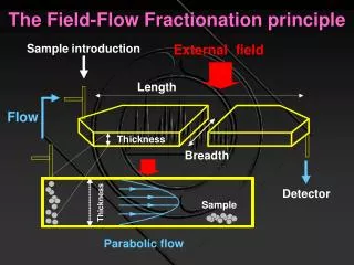
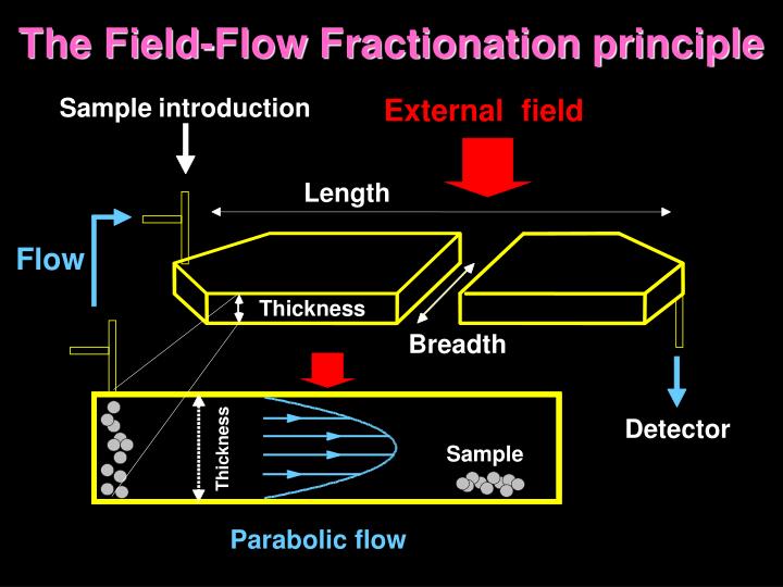
Sample. introduction. External. field. The Field-Flow Fractionation principle. Length. Flow. Thickness. Breadth. Detector. Thickness. Sample. Parabolic flow. SOME APPLICATIONS OF FFF. FFF retention in normal mode. Field. x. Flow. w. <v>. C(x). l. C 0. é. ù. 2. æ. ö. x.

E N D
Sample introduction External field The Field-Flow Fractionation principle Length Flow Thickness Breadth Detector Thickness Sample Parabolic flow
FFF retention in normal mode Field x Flow w <v> C(x) l C0 é ù 2 æ ö x x Flow = < > - ç ÷ V 6 v ê ú w è w ø ê ú ë û - = / x l c x c e ( ) Field 0
é ù 2 æ ö x x = < > - ç ÷ V 6 v ê ú w è w ø ê ú ë û Basic theory in normal FFF ( ) - = x / l c x c e 0 Retention Mean layer thickness l D é ù V V 1 l = = = o = = l - l @ l R 6 coth 2 6 ê ú w Uw < > l ë û V v 2 r kT = D ph 6 r = F fU Potentially ABSOLUTE TECHNIQUE kT l = Fw
FFF retention in reversed mode Field Lift forces Flow d w x æ ¶ ö log V a a t = r = g ç - = 0 S S ÷ R 6 1 R d ç d ¶ d log d t w w ø è 1 r
d ln V = r S d ln M D N R = R s 4 R D N d ln V M = r R s 4 d ln M M k k ' ' D D K K + + 1 1 k k ' ' K K Selectivity and Resolution in FFF Selectivity Normal mode Normal mode St/Hyp mode St/Hyp mode Normal mode Normal mode St/Hyp mode St/Hyp mode Normal mode Normal mode St/Hyp mode St/Hyp mode S= 1 S= 1 S= 1 S= 1 Sd Sd FFF FFF Sd Sd FFF FFF 1.0 1.0 1.0 1.0 1.0 1.0 ) ) ) Resolution ) S= 0.6 S= 0.6 S= 0.6 S= 0.6 dlnM dlnM dlnM dlnM / / / / R R R R ThFFF ThFFF ThFFF ThFFF Transit. Transit. dlnV dlnV Transit. Transit. dlnV dlnV 0.5 0.5 FlFFF FlFFF 0.5 0.5 0.5 0.5 FlFFF FlFFF zone zone zone zone Selectivity ( Selectivity ( Selectivity ( Selectivity ( S S = 0.9 = 0.9 S S = 0.9 = 0.9 d d d d GrFFF S= 0.1 S= 0.1 S= 0.1 S= 0.1 SEC SEC SEC SEC 0 0 0 0 0 0 Selectivity Efficiency 3 3 5 5 7 7 9 9 11 11 13 13 15 15 17 17 3 3 5 5 7 7 9 9 11 11 13 13 15 15 17 17 3 3 5 5 7 7 9 9 11 11 13 13 15 15 17 17 Log MW Log MW Log MW Log MW
Gravitational FFF Sample Sample outlet Injectionvalve Clamping frame Spacer Channelwall
GrFFF of E.coli Sample: CS5 0398 (fimbriated) Number of cells/mL in the 1:1 sample = 4.44 107 Sample: CS5 001101-5 (non-fimbriated) Number of cells/mL in the 1:1 sample = 7.25 106 Carrier: 80% 0.05% w/v SDS, 0.01% w/v NaN3 20% MeOH Detection: UV-Vis detector @ 600 nm; 260 nm Injection volume: 20 µL Injection flow rate: 0.2 mL/min Injection time: 25 s Stop flow time: 30-40 min Elution flow rate: 0.2-0.3 mL/min CS5 001101-5 (non-fimbriated) CS5 0398 (fimbriated)
Detector Response (2) (1) 0 5 10 15 20 Retention time (min) E.coli sorting by GrFFF Fimbriated CS5 0398 (1) 0.44 104 cells (2) 2.22 104 cells Elution flow rate = 0.3 mL min-1 Stop-flow time= 15 min (a) Fimbriated CS5 0398 (b) Non fimbriated XC113A2 (c) Non fimbriated CS5 001101-5 Repeated runs reported for each case (b) DetectorResponse (c) • Non fimbriated 001101-5 • 0.3 mL min-1 • 0.6 mL min-1 (a) 0 10 20 30 40 Retention time (min)
O - C O O H C O O H H O , O H 2 2 N H + light N H - - HRP C O O C O O N H N H N H O 2 2 2 luminol O O O O O M e O M e O C O O M e C O O M e AP + light -- H P O 4 - - O - -- O O O P O 3 1,2-dioxetane Chemiluminescence detection in GrFFF • High signal/mass ratio • Long-lasting emission (glow kinetics) Horseradish peroxidase (HRP) Alkaline phosphatase (AP)
excited 3-aminophthalate intermediate H O products 2 H O 2 2 Enzyme-coated particles Where is CL localized? 3-aminophthalate + light HRP luminol PS HRP-catalyzed oxidation of luminol CL emission takes place in solution: the CL signal is localized on the enzyme-coated beads if the lifetime of the excited, CL-emitting product is shorter compared to its diffusion rate
0.75 0.75 In situ GrFFF-CL Instrumental layout CCD Slow-scan, ultrasensitive cooled CCD camera for sequential image acquisition Pump GFFF channel Mobile phase with CL substrate Injection valve CL substrates in the mobile phase to reduce extra-column band broadening CL images collection: visualization of the fractionation of free/particle-bonded analytes
In situ GrFFF-CL Real-time imaging of the analyte fractionation Channel inlet Direct analysis of sample relaxation Direct evaluation of sample recovery and particle wall-interactions Injection Information on the fractionation process from band profiles optimization and kinetic studies Direct analysis of non-ideality effects Elution
In situ GrFFF-CL Real-time imaging of free HRP + PS/HRP fractionation Sample: 1.25 ng HRP e 7.5 mg PS/HRP 6 mm
FFF a campo idrodinamico (FlFFF) Flusso in ingresso nel canale (iniezione del campione) Flusso trasversale Flusso in uscita dal canale (al rivelatore) Plexiglass Frit poroso Spacer Membrana opzionale Frit poroso Plexiglass Flusso trasversale
Sistema FlFFF Canale FlFFF
Meccanismo FlFFF flusso trasversale flusso trasversale flusso di campione in uscita flusso di campione in entrata profilo parabolico C A B parete di accumulazione (membrana opzionale) parete di deplezione flusso trasversale in uscita Ritenzione in FlFFF La ritenzione dipende solo dalle dimensioni
FlFFF in modo normaleSeparazione di 3 lattici PS Condizioni sperimentali · V cm = 1 . 98 / min · 3 cm V = 0 . 70 / min c 0.08 V0 = 1.11 mL 155 nm 3 cm w = 0 . 02 t0 = 298 K T 0.06 Turbidità 54 nm 102 nm 0.04 0.02 0.00 10 0 5 15 20 tr [min]
Injected sample: mixture of PS/HRP 6/3 mm and PS 10/4 mm Injected sample: 5 mg PS/HRP 6 mm + 5 mg PS/AP 3 mm Reversed FlFFF-CL
Hollow-Fiber FlFFF: miniaturization Flow Flow Field 1/8” PE fitting 1/8” PE Tee 1/8” Teflon tube cPVC / PSfHF membrane 24x0.08 ID cm 1/8” PEEK ferrule 1/8” PEEK ferrule
< > v HF FlFFF in normal mode z L rf Flow l C(z) C0 x U Field
HF FlFFF in reversed mode rf Flow Lift d Field
d + g l 4 R 2 rf HF FlFFF retention Normal mode Reversed mode Normal/reversedmode
HF FlFFF of V. cholerae Void Membrane: PSf 30,000 Da Serotypes:Inaba,Ogawa Injected cells~ 5 106 (in 5 µl) Mobile phase: FL-70 0.1% NaN3 0.02% Focusing time: 3 min Vrad = 51 µl/minVin = 1.5 ml/min UV/Vis signal (mAU) tr (min)
HF FlFFF of HRBCRecoveryandDetectability Membrane: cPVC 30,000 Da Mobile phase: Isotonic PBS (300 mOsm) Cholic acid 1mM Vin = 3.00 ml/min Vrad = 0.27 ml/min Injected cells: 70,000 Area = 8.52 10-3 min Recovery = 68% 7,000 Area = 0.669 10-3 min Recovery = 78% Void
HF FlFFF of winemaking yeast Void Membrane: PSf 30,000 Da Mobile phase: FL-70 0.1% NaN3 0.002% TRIS 0.125% Focusing time: 6 min Vin= 3 ml/min Vrad= 0.44 ml/min PS standards Sd=1.50±0.10 S. cerevisiae HF FlFFF-based size=4.8±0.3 µm S. cerevisiae