Download
1 / 59
660 likes | 1.46k Views
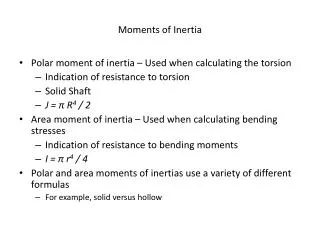
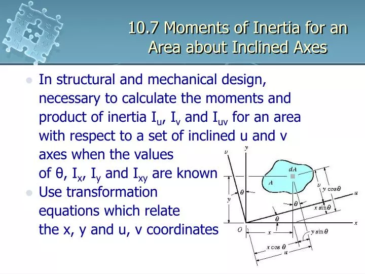
10.7 Moments of Inertia for an Area about Inclined Axes. In structural and mechanical design, necessary to calculate the moments and product of inertia I u , I v and I uv for an area with respect to a set of inclined u and v axes when the values

E N D
10.7 Moments of Inertia for an Area about Inclined Axes • In structural and mechanical design, necessary to calculate the moments and product of inertia Iu, Iv and Iuv for an area with respect to a set of inclined u and v axes when the values of θ, Ix, Iy and Ixy are known • Use transformation equations which relate the x, y and u, v coordinates
10.7 Moments of Inertia for an Area about Inclined Axes • For moments and product of inertia of dA about the u and v axes,
10.7 Moments of Inertia for an Area about Inclined Axes • Integrating, • Simplifying using trigonometric identities,
10.7 Moments of Inertia for an Area about Inclined Axes • Polar moment of inertia about the z axis passing through point O is independent of the u and v axes
10.7 Moments of Inertia for an Area about Inclined Axes Principal Moments of Inertia • Iu, Iv and Iuv depend on the angle of inclination θ of the u, v axes • To determine the orientation of these axes about which the moments of inertia for the area Iu and Iv are maximum and minimum • This particular set of axes is called the principal axes of the area and the corresponding moments of inertia with respect to these axes are called the principal moments of inertia
10.7 Moments of Inertia for an Area about Inclined Axes Principal Moments of Inertia • There is a set of principle axes for every chosen origin O • For the structural and mechanical design of a member, the origin O is generally located at the cross-sectional area’s centroid • The angle θ = θp defines the orientation of the principal axes for the area. Found by differentiating with respect to θ and setting the result to zero
10.7 Moments of Inertia for an Area about Inclined Axes Principal Moments of Inertia • Therefore • Equation has 2 roots, θp1 and θp2 which are 90° apart and so specify the inclination of the principal axes
10.7 Moments of Inertia for an Area about Inclined Axes Principal Moments of Inertia
10.7 Moments of Inertia for an Area about Inclined Axes Principal Moments of Inertia • Depending on the sign chosen, this result gives the maximum or minimum moment of inertia for the area • It can be shown that Iuv = 0, that is, the product of inertia with respect to the principal axes is zero • Any symmetric axis represent a principal axis of inertia for the area
10.7 Moments of Inertia for an Area about Inclined Axes Example 10.9 Determine the principal moments of inertia for the beam’s cross-sectional area with respect to an axis passing through the centroid.
10.7 Moments of Inertia for an Area about Inclined Axes View Free Body Diagram Solution • Moment and product of inertia of the cross-sectional area with respect to the x, y axes have been computed in the previous examples • Using the angles of inclination of principal axes u and v • Thus,
10.7 Moments of Inertia for an Area about Inclined Axes Solution • For principal of inertia with respect to the u and v axes • or
10.7 Moments of Inertia for an Area about Inclined Axes Solution • Maximum moment of inertia occurs with respect to the selected u axis since by inspection, most of the cross-sectional area is farthest away from this axis • Maximum moment of inertia occurs at the u axis since it is located within ±45° of the y axis, which has the largest value of I
10.8 Mohr’s Circle for Moments of Inertia • It can be found that • In a given problem, Iu and Iv are variables and Ix, Iy and Ixy are known constants • When this equation is plotted on a set of axes that represent the respective moment of inertia and the product of inertia, the resulting graph represents a circle
10.8 Mohr’s Circle for Moments of Inertia • The circle constructed is known as a Mohr’s circle with radius and center at (a, 0) where
10.8 Mohr’s Circle for Moments of Inertia Procedure for Analysis Determine Ix, Iy and Ixy • Establish the x, y axes for the area, with the origin located at point P of interest and determine Ix, Iy and Ixy Construct the Circle • Construct a rectangular coordinate system such that the abscissa represents the moment of inertia I and the ordinate represent the product of inertia Ixy
10.8 Mohr’s Circle for Moments of Inertia Procedure for Analysis Construct the Circle • Determine center of the circle O, which is located at a distance (Ix + Iy)/2 from the origin, and plot the reference point a having coordinates (Ix, Ixy) • By definition, Ix is always positive, whereas Ixy will either be positive or negative • Connect the reference point A with the center of the circle and determine distance OA (radius of the circle) by trigonometry • Draw the circle
10.8 Mohr’s Circle for Moments of Inertia Procedure for Analysis Principal of Moments of Inertia • Points where the circle intersects the abscissa give the values of the principle moments of inertia Imin and Imax • Product of inertia will be zero at these points Principle Axes • To find direction of major principal axis, determine by trigonometry, angle 2θp1, measured from the radius OA to the positive I axis
10.8 Mohr’s Circle for Moments of Inertia Procedure for Analysis Principle Axes • This angle represent twice the angle from the x axis to the area in question to the axis of maximum moment of inertia Imax • Both the angle on the circle, 2θp1, and the angle to the axis on the area, θp1must be measured in the same sense • The axis for the minimum moment of inertia Imin is perpendicular to the axis for Imax
10.8 Mohr’s Circle for Moments of Inertia Example 10.10 Using Mohr’s circle, determine the principle moments of the beam’s cross-sectional area with respect to an axis passing through the centroid.
10.8 Mohr’s Circle for Moments of Inertia View Free Body Diagram Solution Determine Ix, Iy and Ixy • Moments of inertia and the product of inertia have been determined in previous examples Construct the Circle • Center of circle, O, lies from the origin, at a distance
10.8 Mohr’s Circle for Moments of Inertia Solution • With reference point A (2.90, -3.00) connected to point O, radius OA is determined using Pythagorean theorem Principal Moments of Inertia • Circle intersects I axis at points (7.54, 0) and (0.960, 0)
10.8 Mohr’s Circle for Moments of Inertia Solution Principal Axes • Angle 2θp1 is determined from the circle by measuring CCW from OA to the direction of the positive I axis
10.8 Mohr’s Circle for Moments of Inertia Solution • The principal axis for Imax = 7.54(109) mm4 is therefore orientated at an angle θp1 = 57.1°, measured CCW from the positive x axis to the positive u axis • v axis is perpendicular to this axis
10.9 Mass Moment of Inertia • Mass moment of inertia of a body is the property that measures the resistance of the body to angular acceleration • Mass moment of inertia is defined as the integral of the second moment about an axis of all the elements of mass dm which compose the body Example • Consider rigid body
10.9 Mass Moment of Inertia • For body’s moment of inertia about the z axis, • Here, the moment arm r is the perpendicular distance from the axis to the arbitrary element dm • Since the formulation involves r, the value of I is unique for each axis z about which it is computed • The axis that is generally chosen for analysis, passes through the body’s mass center G
10.9 Mass Moment of Inertia • Moment of inertia computed about this axis will be defined as IG • Mass moment of inertia is always positive • If the body consists of material having a variable density ρ = ρ(x, y, z), the element mass dm of the body may be expressed as dm = ρ dV • Using volume element for integration,
10.9 Mass Moment of Inertia • In the special case of ρ being a constant, • When element volume chosen for integration has differential sizes in all 3 directions, dV = dx dy dz • Moment of inertia of the body determined by triple integration • Simplify the process to single integration by choosing an element volume with a differential size or thickness in 1 direction such as shell or disk elements
10.9 Mass Moment of Inertia Procedure for Analysis • Consider only symmetric bodies having surfaces which are generated by revolving a curve about an axis Shell Element • For a shell element having height z, radius y and thickness dy, volume dV = (2πy)(z)dy
10.9 Mass Moment of Inertia Procedure for Analysis Shell Element • Use this element to determine the moment of inertia Iz of the body about the z axis since the entire element, due to its thinness, lies at the same perpendicular distance r = y from the z axis Disk Element • For disk element having radius y, thickness dz, volume dV = (πy2) dz
10.9 Mass Moment of Inertia Procedure for Analysis Disk Element • Element is finite in the radial direction and consequently, its parts do not lie at the same radial distance r from the z axis • To perform integration using this element, determine the moment of inertia of the element about the z axis and then integrate this result
10.9 Mass Moment of Inertia Example 10.11 Determine the mass moment of inertia of the cylinder about the z axis. The density of the material is constant.
10.9 Mass Moment of Inertia Solution Shell Element • For volume of the element, • For mass, • Since the entire element lies at the same distance r from the z axis, for the moment of inertia of the element,
10.9 Mass Moment of Inertia Solution • Integrating over entire region of the cylinder, • For the mass of the cylinder • So that
10.9 Mass Moment of Inertia Example 10.12 A solid is formed by revolving the shaded area about the y axis. If the density of the material is 5 Mg/m3, determine the mass moment of inertia about the y axis.
10.9 Mass Moment of Inertia Solution Disk Element • Element intersects the curve at the arbitrary point (x, y) and has a mass dm = ρ dV = ρ (πx2)dy • Although all portions of the element are not located at the same distance from the y axis, it is still possible to determine the moment of inertia dIy about the y axis
10.9 Mass Moment of Inertia Solution • In the previous example, it is shown that the moment of inertia for a cylinder is I = ½ mR2 • Since the height of the cylinder is not involved, apply the about equation for a disk • For moment of inertia for the entire solid,
10.9 Mass Moment of Inertia Parallel Axis Theorem • If the moment of inertia of the body about an axis passing through the body’s mass center is known, the moment of inertia about any other parallel axis may be determined by using parallel axis theorem • Considering the body where the z’ axis passes through the mass center G, whereas the corresponding parallel z axis lie at a constant distance d away
10.9 Mass Moment of Inertia Parallel Axis Theorem • Selecting the differential mass element dm, which is located at point (x’, y’) and using Pythagorean theorem, r 2 = (d + x’)2 + y’2 • For moment of inertia of body about the z axis, • First integral represent IG
10.9 Mass Moment of Inertia Parallel Axis Theorem • Second integral = 0 since the z’ axis passes through the body’s center of mass • Third integral represents the total mass m of the body • For moment of inertia about the z axis, I = IG + md2
10.9 Mass Moment of Inertia Radius of Gyration • For moment of inertia expressed using k, radius of gyration, • Note the similarity between the definition of k in this formulae and r in the equation dI = r2 dm which defines the moment of inertia of an elemental mass dm of the body about an axis
10.9 Mass Moment of Inertia Composite Bodies • If a body is constructed from a number of simple shapes such as disks, spheres, and rods, the moment of inertia of the body about any axis z can be determined by adding algebraically the moments of inertia of all the composite shapes computed about the z axis • Parallel axis theorem is needed if the center of mass of each composite part does not lie on the z axis
10.9 Mass Moment of Inertia Example 10.13 If the plate has a density of 8000kg/m3 and a thickness of 10mm, determine its mass moment of inertia about an axis perpendicular to the page and passing through point O.
10.9 Mass Moment of Inertia Solution • The plate consists of 2 composite parts, the 250mm radius disk minus the 125mm radius disk • Moment of inertia about O is determined by computing the moment of inertia of each of these parts about O and then algebraically adding the results
10.9 Mass Moment of Inertia Solution Disk • For moment of inertia of a disk about an axis perpendicular to the plane of the disk, • Mass center of the disk is located 0.25m from point O
10.9 Mass Moment of Inertia Solution Hole • For moment of inertia of plate about point O,
10.9 Mass Moment of Inertia Example 10.14 The pendulum consists of two thin robs each having a mass of 100kg. Determine the pendulum’s mass moment of inertia about an axis passing through (a) the pin at point O, and (b) the mass center G of the pendulum.
10.9 Mass Moment of Inertia Solution Part (a) • For moment of inertia of rod OA about an axis perpendicular to the page and passing through the end point O of the rob, • Hence, • Using parallel axis theorem,
10.9 Mass Moment of Inertia Solution • For rod BC, • For moment of inertia of pendulum about O,
10.9 Mass Moment of Inertia Solution Part (b) • Mass center G will be located relative to pin at O • For mass center, • Mass of inertia IG may be computed in the same manner as IO, which requires successive applications of the parallel axis theorem in order to transfer the moments of inertias of rod OA and BC to G