Download
1 / 37
370 likes | 595 Views
PESP-2008 Workshop (3. October, 2008 @J-Lab). “High Brightness and High Polarization Electron Source for Electron Microscope”. Tsutomu NAKANISHI ( Department of Physics, Graduate School of Science, Nagoya University).

E N D
PESP-2008 Workshop (3. October, 2008@J-Lab) “High Brightness and High Polarization Electron Sourcefor Electron Microscope” Tsutomu NAKANISHI (Department of Physics, Graduate School of Science, Nagoya University)
Beam requirementsfor electron sources fromthree kinds of electron accelerators High peak current (≥10A) Φ10mm ILC High average current (≥10mA) ERL Φ1mm High current density (≥ 1A/mm2) Φ1μm SPLEEM
Contents of this talkhave already explained partially in1) Talk by Toru Ujihara,[ R/D of transmission PC ]2) Poster by NaotoYamamoto (“small” Y)[ Proto-type SPLEEM gunperformances ]
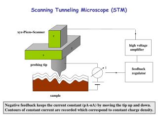
LEEM / PEEM type Electron Microscope (developed by E. Bauer) Energy analyzer ( 90°or180°bend) LaB6 emitter Focus lens Image lens LEEM Objective lens Beam separator Contrast aperture Screen Objective lens hn PEEM Specimen
SPELEEM (大阪電通大、OECU) Koshikawa & Yasue Group CCDカメラ エネルギー分析器 LaB6 Gun 電子銃 電子ビーム コントラスト アパーチャー 高輝度水銀ランプシステム 制限視野 アパーチャー 入射側アパーチャー (イルミネーション アパーチャー) 測定室 試料準備室 マニピュレーター Made by ELMITEC co. (Germany)
0 1 2 3 2.13 2.47 Coverage[MLbcc] LEEM images Dynamic observation of Cu thin film growth on W(110) at 100 ℃ FOV10mmf 0-3.2MLbcc layer-by-layer growth (Room temp. - ~ 150℃) The third layer does not start just after 2.13MLbcc and it start at around 2.47MLbcc.
LEEM contrast : I + Mag. Domain contrast : P M Magnetization of surface M A µ P M I+ = I+ LEEM Image I= I Imaging of magnetic domains Mag. Domain Image A : Magnetic contrast (Asymmetry) P : Polarization of incident beam : • Pure Spin effects can be obtained in Magnetic domain images
Proposal of this work (April 2008) Real-timeobservation of magnetic domain formation process Approved at September 2005 by Japan Science and Technology Agency (JST),asTechnology Development Program for Advanced Measurement and Analysis (Program-T)
talk contents 1. Procedure for Higher Brightness Transmission Type Photocathode 2. A 20keV Test-Gun Apparatus Performances Beam Performances 3. A 20keV gun for SPLEEM Assembling finished Beam test in Progress
Our first trial toward higher brightness(2003) HV=-20kV、gap-width=5.34mm Needle-tip (20nm radius) NEA-GaAs emitter M.Kuwahara et al. JJAP 45 (2006) 6245 ●Field emitter polarized electron source ▲Serious Problem : Current limit ( Tip melt-down by self-heating) (current / tip30 nA)
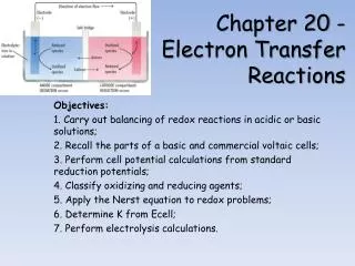
This work toward much higher brightness (2005) Lens f >20cm Photocathode Laser Anode Laser Mirror Electron Electron Lens f=a few mm Photocathode Anode Spherical Condenser Laser Lens f >20cm Electron ▲ Conventional Type Laser spot size 50m ● New transmission type Laser spot size ≈ diffraction limit a few m Advantage : Electron & Laser beam lines do not interfere Laser spot size (exp.) 1.3μm(FWHM) @λ:777nm)
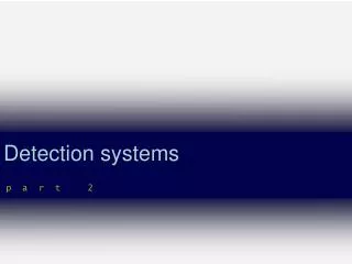
CCD camera Lens stage to make the minimum laser spot Optical Fiber Ti-Sapphire Laser Fiber Collimater Polarizing Beam splitter Quarter Waveplate Imaging Lens Positioner XHV Focusing Lens Focusing Lens Photocathode Photo- cathode Electron Beam
talk contents 1. Procedure for Higher Brightness Transmission Type Photocathode 2. A 20keV Test-Gun Apparatus Performances Beam Performances 3. A 20keV gun for SPLEEM Assembling finished Beam test in Progress
A 20keV test-gun’s Compositions NEA activation chamber Laser optics equipment Gun chamber 100keV-Mott Analyzer Beam size monitor Spherical condenser
Electrode SL-PC Mo Ti Ceramic Beam simulation 20keV adopted ○ Laser spot=φ3μm ○ Electrode gap=4mm ○ Voltage=20kV Field gradient=5MV/m ○ Electrode:Mo (cathode) materialTi (anode) ○ Photocathode exchanged by a load-lock system Beam simulation 4keV Dark current could be suppressed below 10nA under 25kV
Apparatus performance of JPES-1 Gun assembly Activation chamber Load-lock transfer-rod
Gun knife-edge L Farady cup 2 1 L 1 Reduced Brightness B I r π π 2 2 S U R S Beam size (Brightness) measurement Conditions:Beam energy (U) = 20keV,Beam current (I)=5.3μA Current (I) Current density (dI/dx) L=531mm Source size (S) estimation = Laser spot size+Electron diffusion length = 0.65μm(HWHM) + 1μm ~1.5±0.3μm Beam size R=1.00±0.02mm (HWHM) =1.0±0.4×10⁷ A m-2 sr-1 V-1
Performance of GaAs-GaAsP superlattice (Reflection PC by Nagoya group) @778nm ☆GaAs-GaAsP superlattice shows the best performance ! Polarization~ 92% Q.E.~ 0.5%
Transmission PC 90% Polarization achieved (2007/10/26) Position dependence of Polarization Uniformity of Polarization assured
Polarization improvement by change of strain property of GaAsP buffer-layer Pol. 65% Pol. 90%
Summary of JPES-1Performances Performances of 20keV polarized electron gun with transmission type photocathode (PC) • Beam size at PC 1.3m (780nm laser) • Polarization ≥ 90% • Quantum efficiency ≥ 0.1% • Average Current ≥ 15A • Brightness ≥ 2107A/cm2/str (@20keV) • Brightness (reduced) ≥ 1107A/m2/str/V • NEA lifetime ≥ 200h (without beam) • NEA lifetime ≥ 30h (with 5 A) • Vacuum at PC 9.0 10-10 Pa
Documents on a transmission PC PES [Doctor Thesis]Naoto Yamamoto: “NEA-GaAs型超格子薄膜結晶を用 い た高輝度・高スピン偏極度・大電流密度ビームを生成する電子源の開発” (Nagoya University、2007年度) [Published Papers] (1)“High brightness and high polarization electron source using transmission photocathode with GaAs-GaAsP superlattice layers“ N. Yamamoto et al. Journal of Applied Physics vol.103, (2008), 064905 (2) “Super-high brightness and high spin-polarization photocathode” X. Jin et al. Applied Physics Express Vol. 1 (2008), Article No.: 045002 • [Patents] • T. Nakanishi: “スピン偏極電子源装置”、特願 2006-084303 • T. Ujihara、T. Nakanishi 他5名:“透過光吸収フォトカソード型偏極電子源”、特願2008-079292(2008/3/25出願)
talk contents 1. Procedure for Higher Brightness Transmission Type Photocathode 2. A 20keV Test-Gun Apparatus Performances Beam Performances 3. A 20keV gun for SPLEEM Assembling finished and final beam test in progress
High Brightness & High Polarization Electron Source for LEEM LEEM (Osaka) PES (Nagoya) Within one month, this PES system will be transferred to Osaka and jointed with LEEM
Additional remarks(1) ○ Advantages of transmission-PC PES • Freedom to design both of laser & electron beam • Lines independently. Laser beam line can be optimized to satisfy various requirements. • Minimum laser spot size obtained (this work) • Symmetrical beam distribution to beam axis • Relax the laser heating problem for ERL-PC • Two photon excitation becomes easily. • Others, etc. etc. …..
Possible applications of the new-type PES We start to contact with various fields researchers (Looking for the academic users of our PES) [Biology] Chirality studies [SPLEEM] Surface magnetic domain Magnetic memories [TEM] Bulk magnetic properties Electron holography [HE Accelerators] High current + low emittance electron source [Inverse Photo-emission Spectroscopy] Spin IPES
SPLEEM collaboration T. Nakanishi, S. Okumi, M. Yamamoto, [M. Kuwahara], [N. Yamamoto], [A. Mano], Y. Nakagawa (Faculty of Science, Nagoya University) Y. Takeda, T. Ujihara, X. J. Kim (Faculty of Engineer, Nagoya University) T. Saka (Daido Institute of Technology) T. Kato (Daido Steel Co. Ltd.) T. Koshikawa, T. Yasue, M. Suzuki (Osaka Electro-Communication University) T. Ohshima、T. Kohashi (Central Research Laboratory, Hitachi Ltd.) High Energy Physics Semiconductor Physics LEEM Physics Electron Microscope Physics
Thanks for your attentions !
Co : 4 ML W(110) φ θ P M A µ P M 2 m θ Electron injection energyEi=0.7 [eV]、50 [sec/image] Examples of SPLEEM image FOV=30 [m] FOV=10 [m] FOV=6 [m] φ
Mechanisms of spin-flip depolariztion GaAs-substrate Crystal defects of buffer-layer carried onto SL-layer GaP-substrate GaAs-substrate Spin-flip occurs Spin-flip does not occur SL-layers GaAsP buffer-layer GaP-substrate Cracks do not meet with electrons Dislocations meet with electrons Crack-like defects are favorable than dislocation-like defects